
Warning: The vehicles described in this manual are equipped with a Supplemental Restraint System (SRS), also known as an air bag system. Before carrying out work in the area where the elements of this system are located, it is necessary to disconnect its power supply, since accidental deployment of the airbags can result in serious injury (see chapter 12).
Note: This procedure is time-consuming and labor-intensive, even for an experienced auto mechanic. Because the instrument panel contains many electrical connectors and safety system components, and because it has many small fasteners, it is not recommended to remove it yourself.
1. Set the front wheels in the straight-ahead direction and lock the steering column, then disconnect the negative battery cable (see chapter 1).
2. Turn off the power supply to the SRS system (see chapter 12).
Upper trim panel of the instrument panel
3. Using a suitable tool, detach the inner trim strips of the windshield pillars.
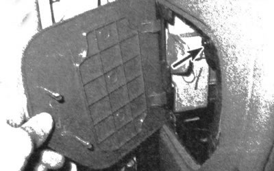
4. Carefully pull out the clips located along the upper trim panel of the instrument panel (see illustration).
26.4. Carefully pry and detach the upper trim panel from the instrument panel
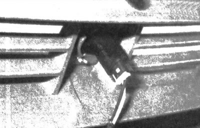
5. Locate the light sensor, which is located in the center of the top trim panel. Turn the sensor 1 2/4 turns counterclockwise to disengage it from the trim panel, then remove the trim panel from the instrument panel (see illustration).
26.5. Turn the outer axle level sensor counterclockwise to the trim panel
6. Installation is carried out in the reverse order of removal.
Instrument panel
7. Turn off the power supply to the SRS system (see chapter 12).
8. Remove the upper instrument panel trim panel (see above).
9. Remove the center console (see subsection 23).
10. Remove all panels as described in subsection 24. It is also necessary to remove the instrument panel (see chapter 12).
11. Disconnect the steering column from the instrument panel and lower it (see chapter 10). If the instrument panel support structure is to be removed, remove the entire steering column.
12. Remove the left heater duct (see chapter 10, illustration 17.7).
13. Remove the radio receiver (see chapter 12) If the design provides for the presence of front overhead speakers, remove them.
14. Remove the heater/air conditioner control panel and disconnect its wiring harness from the holder (see chapter 3)
15. Remove the covers located on each edge of the instrument panel, then B;, turn the screws that secure each end (see illustration)

26.15. Detach the cover located on each side of the instrument panel and unscrew the screw located underneath it
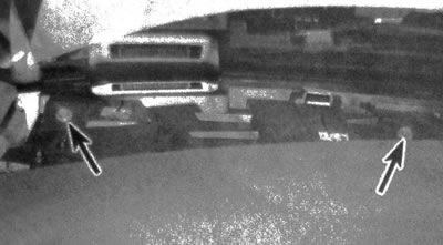
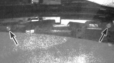
16. Unscrew the lower mounting bolts located on the right side of the instrument panel, as well as the bolts located in the center (radio receiver opening), and the bolts that are located in the instrument panel opening (see illustrations).
26.16a. Remove the screws located at the bottom right of the instrument panel...
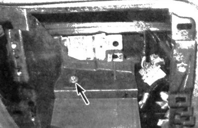
26.16b....and also the screw located in the opening of the radio receiver
26.16s....and screws located in the instrument panel opening
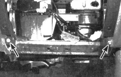
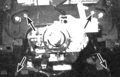
17. Remove the bolts located along the top edge of the instrument panel (see illustrations).
26.17a. Remove the screws located on the top left edge of the instrument panel...
26.17b....and on the right edge, then make sure all the elements are disconnected and remove the instrument panel
18. Ask an assistant for help and remove the instrument panel
19. Installation is carried out in the reverse order of removal.
Instrument panel holder
20. The instrument panel holder is a complex component that supports the steering column, heater/air conditioner control panel and other components. The bracket is removed together with the HVAC module, which contains the heater core and the air conditioner evaporator (see chapter 3).