


The gearbox parts are shown in Figure 3-63.
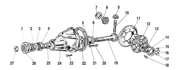
Figure 3-63. Rear axle gearbox parts:
1 - drive gear flange;
2 - oil seal;
3 - oil deflector;
4 - front bearing;
5 - rear bearing;
6 - drive gear adjusting ring;
7 - axle gear support washer;
8 - axle shaft gear;
9 - satellite;
10 - satellite axis;
11 - driven gear;
12 - differential box;
13 - differential box bearing;
14 - adjusting nut;
15 - lock plate mounting bolt;
16 - locking plate;
17 - locking plate;
18 - driven gear mounting bolt;
19 - drive gear;
20 - cover mounting bolt;
21 - spring washer;
22 - gasket;
23 - gearbox mounting bolt;
24 - gearbox housing;
25 - spacer sleeve;
26 - flat washer;
27 - drive gear flange fastening nut.
Differential assembly. Lubricate with transmission oil and install through the windows into the differential box the axle shaft gears with support washers and satellites. Turn the satellites and axle shaft gears so as to align the axis of rotation with the axis of the hole in the box, then insert the axis of the satellites.
Check the axial clearance of each axle gear: it should be 0-0.10 mm, and the torque of resistance to rotation of the differential gears should not exceed 14.7 Nm (1.5 kgf·m).
If the clearance is increased, which is a sign of wear of the differential components, replace the axle gear support washers with others of greater thickness. If the specified clearance cannot be achieved even when installing the washer of the greatest thickness, replace the gears with new ones due to their excessive wear.
Secure the driven gear to the differential case.
Using mandrel A.70152, press the inner rings of the roller bearings onto the differential box.
Original version of the article on the website «ChevyMan.ru»