


Secure the device to the gearbox housing with screws 1 and 6, screwing them into the holes for the bolts securing the locking plates of the adjusting nuts.
Move bracket 7 along the guide of the device until lever 5 touches the outer side surface of the cover and tighten screw 8.
Loosen screws 1 and 3 (figure 3-72) and install bracket 4 so that the indicator leg 2 rests on the side surface of the driven gear tooth at the edge of the tooth, then tighten screws 1 and 3.
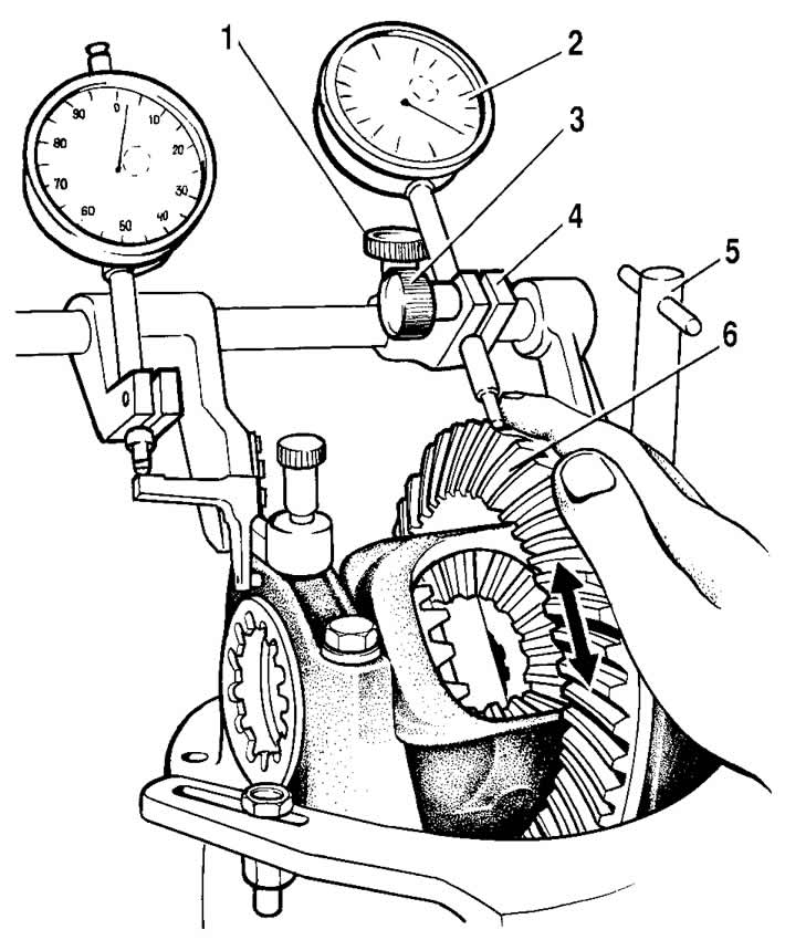
Figure 3-72. Checking the lateral clearance in the engagement of the main transmission gears using the A.95688/P device:
1 - bracket mounting screw;
2 - indicator for checking the lateral clearance in the engagement of gears;
3 - screw for fastening the indicator rod;
4 - indicator bracket;
5 - mounting screw;
6 - driven gear.
By turning the adjusting nuts, pre-adjust the lateral clearance between the teeth of the driving and driven gears within 0.08-0.13 mm. The clearance is checked using indicator 2 while rocking gear 6. In this case, the bearings should not have a pre-tension. The adjusting nuts should only be in contact with the bearings, otherwise the correct measurement of the pre-tension is disrupted.
Tighten the two bearing adjusting nuts in sequence and evenly, causing the differential bearing caps to move apart and therefore increasing the distance "D" (figure 3-73) by 0.14-0.18 mm.
Having set the exact preload of the differential box bearings, finally check the lateral clearance in the engagement of the main gear gears, which should not change.
If the clearance in the gear engagement is greater than 0.08-0.13 mm, then move the driven gear closer to the driving gear or move it away if the clearance is smaller. To maintain the set bearing preload, move the driven gear by tightening one of the bearing adjusting nuts and loosening the other by the same angle.
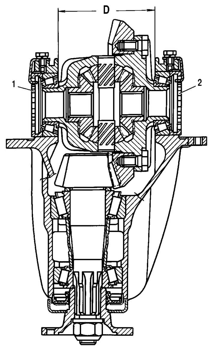
Figure 3-73. Schematic diagram for checking the differential box bearing preload:
D - distance between two differential bearing caps;
1, 2 - adjusting nuts.
To perform this operation accurately, watch the indicator 9 (see figure 3-71), which shows the value of the previously set bearing preload. After tightening one of the nuts, the indicator reading will change as the "D" divergence increases (see figure 3-73) caps and preload of the bearings. Therefore, loosen the other nut until the indicator arrow returns to its original position.
After moving the driven gear, according to indicator 9 (see figure 3-71) check the side clearance. If the clearance is not within the norm, repeat the adjustment.
Remove the A.95688/R tool, install the adjusting nut locking plates and secure them with the bolts and spring washers. Spare parts come in two types of locking plates: one- or two-jaw, depending on the position of the nut slot.
Adjustment and repair of gearbox units is performed on a stand, where the gearbox can also be tested for noise and the location and shape of the contact patch on the working surfaces of the teeth can be checked, as indicated below.
(Original version of the article on the website: ChevyMan.ru)