
Contents: Checking functionality ↧ Replacement ↧
Warning: See warning in subsection 1.
Checking functionality
1. Remove the tank and fuel pump module (see subsection 5 and 7).
2. Connect the ohmmeter electrodes to the two contact terminals of the measuring unit (1 and 4) located in the fuel pump module connector (see illustration).
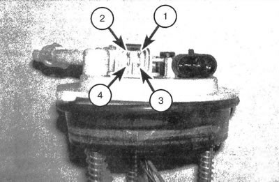
8.2. Elements of a typical fuel system: 1. Receiving a signal from the measuring unit; 2. Supply 12V voltage to the pump (via relay); 3. Grounding; 4. Grounding the measuring unit
3. Place the float in the lower position (corresponding to an empty tank) and take readings from the ohmmeter.
4. Move the float to the upper position (corresponding to a full tank) and observe the change in the instrument readings.
5. If the electrical resistance does not change smoothly when moving the float from the lower to the upper position, replace the measuring unit.
Replacement
6. Remove the fuel tank and fuel pump module (see subsection 5 and 7).
7. Disconnect the electrical connector of the measuring unit from the module casing (see illustration).
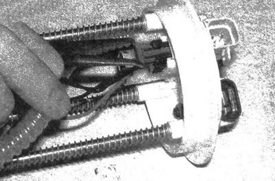
8.7. Disconnect the fuel pump/metering unit electrical connector from the module
8. Remove the measuring block retainer (see illustration).
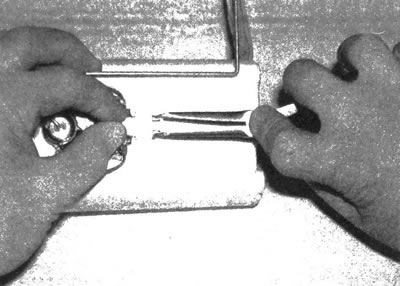
8.8. Remove the measuring block retainer
9. Squeeze the clips and pull the fuel system measuring unit off the module (see illustration). Mark the original order of the wire laying.
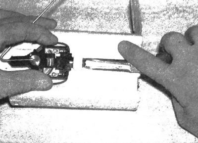
8.9. Squeeze the clamps and remove the fuel system measuring unit from the module
10. Installation is carried out in the reverse order of removal.