
Note: The following procedure assumes that the fuel pressure is normal (see subsection 3).
1. Inspect all electrical connectors related to the system. Make sure the circuits are properly grounded. Loose connectors and poor grounding will manifest as more serious engine problems.
2. Make sure that the battery is fully charged, as the proper operation of the control unit and system sensors is only possible if the supplied voltage complies with the norm.
3. Inspect the air cleaner element. A clogged filter has a negative impact on the engine's performance and fuel economy (see chapter 1).
4. Inspect the system circuit fuses. If the inspection reveals a blown fuse, replace it and make sure it does not blow again. If the fuse blows, find a wire shorted to ground in the wiring harness.
5. Make sure the air intake duct connecting the air cleaner to the throttle body is tight. Depressurization of the air duct leads to a constant depletion of the fuel-air mixture. Also inspect all vacuum hoses connected to the intake manifold/throttle body.
6. Remove the resonator and intake air duct from the throttle body (see subsection 9). Inspect the throttle body for dirt and any deposits in the housing, paying particular attention to the valve. If necessary, clean using a special product, a toothbrush and a cloth.
Caution: Do not clean the throttle body with petroleum solvent as this may damage the component.
7. Locate the 8-pin connector and disconnect it (see illustration). Determine the resistance of each injector by connecting an ohmmeter to terminal "A" and the corresponding terminal (B, C, D, F, G or H) on the connector on the injector side (see illustration). Compare the obtained values with the values given in the specifications of this chapter. Injectors whose resistance does not meet the standard (in the on or off position) are subject to replacement.
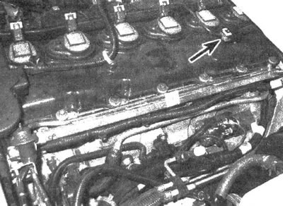
11.7a. Injector Wiring Harness Connector
8. Turn the ignition key to the ON position and measure the voltage at the pink terminal "A" on the connector on the injector wiring harness side (on the engine wiring harness side, measure at the terminal corresponding to terminal "A" in Illustration 11.7b). If there is no voltage from the battery, inspect the corresponding fuse and wire (see chapter 12).
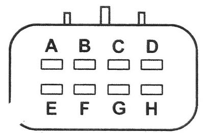
11.7b. 8-pin injector wiring harness connector terminals (connector on the injector side with the plug disconnected): A. Voltage supply from the ignition system (pink); B. Nozzle 4 (blue/black); S. Nozzle 5 (black, white); D. Nozzle 6 (yellow black); E. Empty contact pin; F. Nozzle 1 (black); G. Nozzle 2 (light green/black); N. Nozzle 3 (pink black)
9. A description of further testing of the engine control system performance is given in chapter 6.
[For details, visit the website «CHEVYMAN.RU»]