


Contents: Removal procedure ↧ Installation procedure ↧
Removal procedure
1. Disconnect the negative battery cable.
2. Remove the instrument panel bracket assembly. See section 9E, "Instruments/Driver Information System".
3. Drain the cooling system. See section 1D, "Engine Cooling".
4. Evacuate the refrigerant. See section 7B, "Manually controlled heating, ventilation and air conditioning system".
5. Loosen the mounting nuts holding the suction hose and evaporator liquid pipe connector blocks to the firewall.
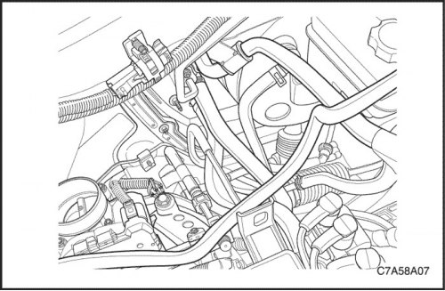
6. Loosen the clamp bolts on the suction hose and liquid pipe of the evaporator so that the hose and pipe can be moved.
7. Remove the evaporator drain hose.
8. Squeeze the heater hose clamps on the firewall and slide the clamps toward the engine.
9. Remove the two heater hoses from the heat exchanger pipes at the firewall.
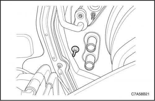
10. Loosen the air conditioner unit screw located under the expansion valve on the firewall on the engine side.
11. An assistant should support the air conditioning unit from inside the vehicle.
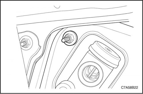
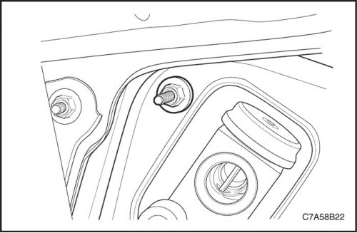
12. Remove the air conditioner unit screw from the evaporator flange on the engine side of the firewall. The air conditioner unit will begin to drop.
13. Pull the body straight away from the fire partition.
14. Remove the air conditioning unit from the vehicle.
Installation procedure
1. Install the air conditioning unit on the vehicle.
Note: To avoid damage to the heater heat exchanger tubes, ensure that they do not touch the edges of the openings in the firewall.
2. Carefully lift the air conditioner unit into place on the firewall and hold it there until the screws on the engine side of the firewall are installed and tightened.
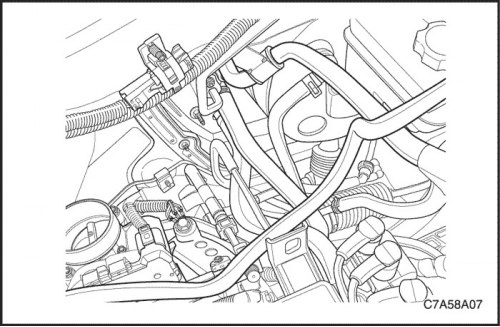
3. Align and insert the A/C unit screws above the fuel filter and onto the evaporator flange.
Tighten
Tighten the air conditioner unit screw to 8 Nm (71 lbs.in).
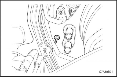
4. Tighten the air conditioner unit screw next to the heater hoses.
Tighten
Tighten the air conditioner unit screw to 8 Nm (71 lbs.in).
5. Install two heater hoses.
6. Slide the heater hose clamps back into place.
7. Install the instrument panel bracket assembly. See section 9E, "Instruments/Driver Information System".
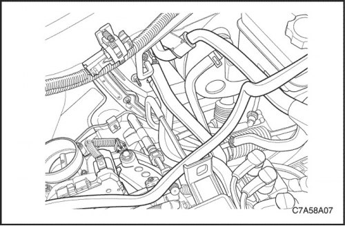
8. Place new O-rings on the evaporator suction hose and liquid tube at the firewall and install the tubes in place.
9. Tighten the mounting nuts that hold the suction hose and evaporator liquid tube connector blocks to the firewall.
Tighten
Tighten the suction hose and liquid pipe evaporator mounting nuts to 16 N·m (12 ft·lbs).
10. Fill the cooling system. See section 1D, "Engine Cooling".
11. Charge the air conditioning system. See section 7B, "Manually controlled heating, ventilation and air conditioning system".
12. Connect the negative battery cable.