
Contents: ABS system circuit (I) ↧ ABS system circuit (II) ↧ Schematic diagram I - ABS ↧ Schematic diagram (II) - ABS with… ↧ View of the Brake System Controller… ↧ ABS (with ESP) pinout ↧ Hydraulic diagram ↧
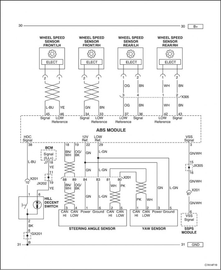
ABS system circuit (I)
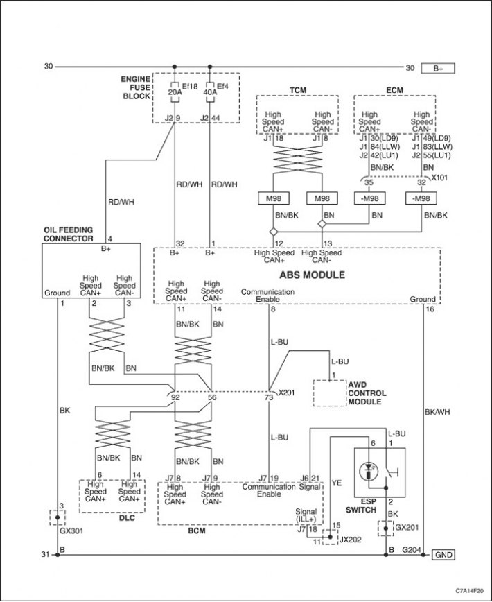
ABS system circuit (II)
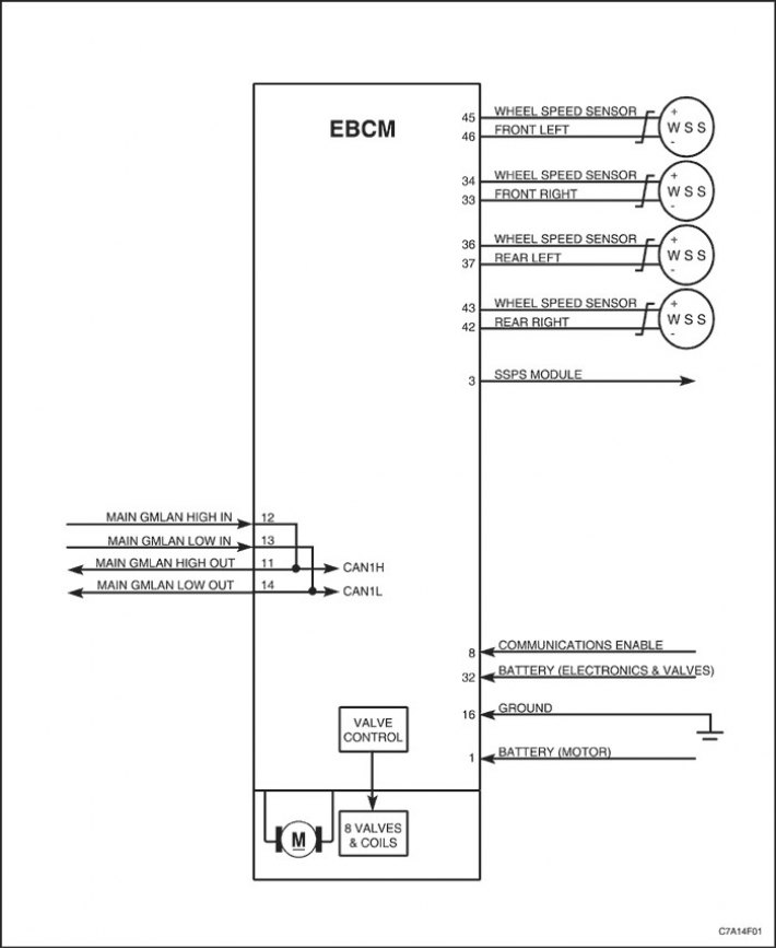
Schematic diagram I - ABS
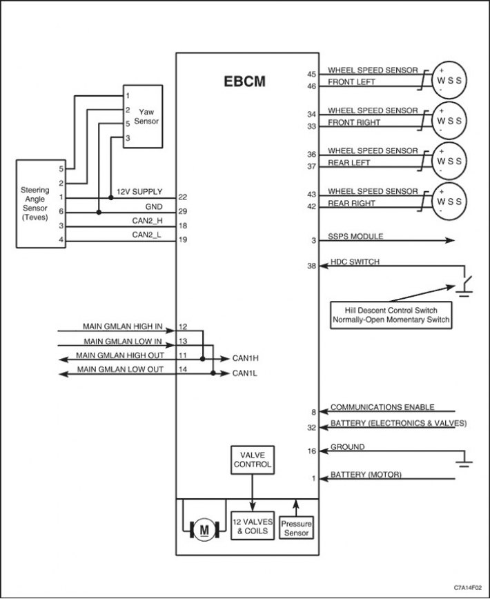
Schematic diagram (II) - ABS with ESP (Electronic stability control system)
View of the Brake System Controller Connection Connector (EBCM) and contact location
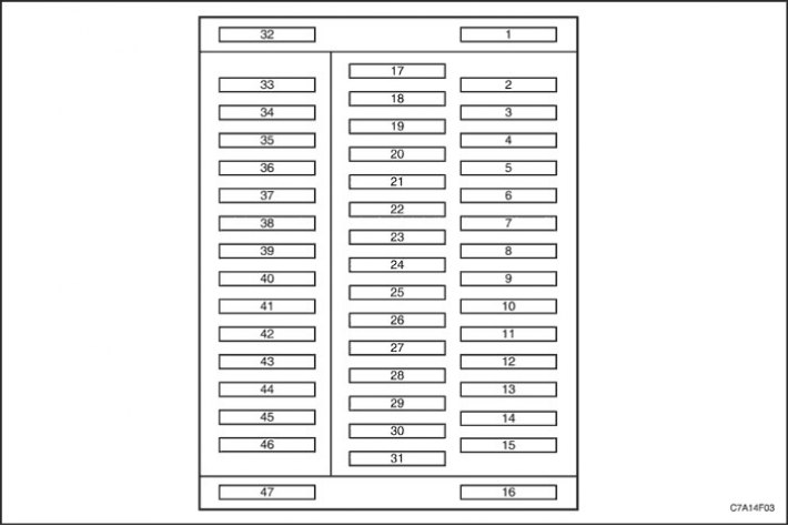
ABS (with ESP) pinout
|
Contact number
|
Function of an electrical circuit
|
|
1
|
Battery (Hydraulic motor)
|
|
2
|
-
|
|
3
|
VSS signal (Steering sensor) from SSPS module (Power steering module that changes the degree of gain with changing driving speed)
|
|
4
|
-
|
|
5
|
-
|
|
6
|
-
|
|
7
|
-
|
|
8
|
The connection is on (Body electronic systems control unit and all-wheel drive control unit)
|
|
9
|
-
|
|
10
|
-
|
|
11
|
GMLAN Main Network - High Speed Output. (high speed CAN bus)
|
|
12
|
GMLAN Main Network - High Speed Input. (high speed CAN bus)
|
|
13
|
GMLAN Main Network - High Speed Input. (low speed CAN bus)
|
|
14
|
GMLAN Main Network - High Speed Output. (low speed CAN bus)
|
|
15
|
-
|
|
16
|
Grounding
|
|
17
|
-
|
|
18
|
Yaw Rate Sensor, High Speed CAN Bus
|
|
19
|
Yaw Rate Sensor, Low Speed CAN Bus
|
|
20
|
-
|
|
21
|
-
|
|
22
|
Yaw rate sensor power supply (base voltage - 12 V)
|
|
23
|
-
|
|
24
|
-
|
|
25
|
-
|
|
26
|
-
|
|
27
|
-
|
|
28
|
-
|
|
29
|
Yaw rate sensor (low base voltage - ground)
|
|
30
|
-
|
|
31
|
-
|
|
32
|
Battery (electronics and valves)
|
|
33
|
Wheel Speed Sensor - Front Right (low base voltage - ground)
|
|
34
|
Wheel Speed Sensor - Front Right (Signal)
|
|
35
|
-
|
|
36
|
Wheel Speed Sensor - Rear Left (Signal)
|
|
37
|
Wheel Speed Sensor - Rear Left (low base voltage - ground)
|
|
38
|
HCD signal (Automatic hill descent control system)
|
|
39
|
-
|
|
40
|
-
|
|
41
|
-
|
|
42
|
Wheel Speed Sensor - Rear Right (low base voltage - ground)
|
|
43
|
Wheel Speed Sensor - Rear Right (Signal)
|
|
44
|
-
|
|
45
|
Wheel Speed Sensor - Front Left (Signal)
|
|
46
|
Wheel Speed Sensor - Front Left (low base voltage - ground)
|
|
47
|
-
|
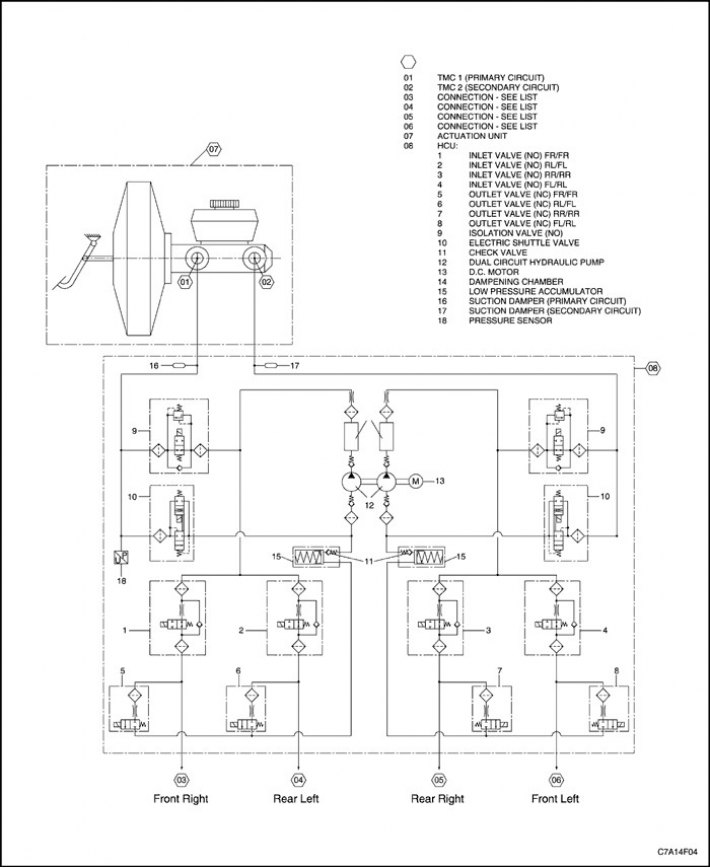
Hydraulic diagram
[Original version of the article on the website: «ChevyMan.ru»]