


Contents: General description of the system ↧ Basic knowledge required ↧ ABS system components ↧ Arrangement of functional blocks ↧ HECU (hydraulic block controller) ↧ Solenoid valve relay ↧ Wheel speed sensors and toothed rings ↧ ABS warning light ↧ Brake warning light ↧ Electronic Stability Program (ESP) ↧ EBD (electronic Brakeforce… ↧ HBA (auxiliary hydraulic brake) ↧ DSC (automatic hill descent control… ↧
General description of the system
The ABS/TCS/ESP systems include several functional units and provide the volumetric pressure flow required to change the braking torque in response to wheel slip information received from the wheel speed sensors. The traction control braking system (TCS) is designed to create a moment of stability on the driven wheel rotating with the greatest slip or to reduce slip on both driven wheels, thereby optimizing the traction of the other driven wheel or driven wheels. The electronic stability program (ESP) ensures vehicle stability when the vehicle deviates from a set steering angle. This system is designed to match the yaw motion of the vehicle to the driver's intentions. In addition to the signals generated by the wheel speed sensors provided for controlling the ABS/TCS systems, the signals of the lateral acceleration sensor, yaw rate sensor, steering angle sensor and pressure sensor are also required as input parameters for controlling the ESP system. In addition, these systems may include Electronic Brake-force Distribution (EBD) to regulate effective braking force on the rear wheels instead of the traditional proportional valve.
The MK25E is a housing with electromagnetic valves, an integrated pump and an ECU controller. Each brake circuit consists of a pair of valves (normally open inlet valve / normally closed outlet valve), providing a change in braking pressure on the front wheels (individual wheel control) and on the rear wheels (it is necessary to select a low control level or stability control with the ABS plus system) in response to appropriate electrical signals.
The TCS ICU system consists of the MK25E ABS with additional elements in the valve block for braking intervention during TCS operation and active yaw control (item 3.1). The shut-off valves with integrated relief valve in the TCS valve block provide an increase in brake pressure for TCS/ESP control via the pump, bypassing the actuation unit. Using electrical selector valves (ESV), the pump intake is switched from the low-pressure accumulators to the TMC system. The intake throttles optimize the pump intake characteristics and reduce the impact of the switchover at the end of the TCS control cycle.
Basic knowledge required
Before you begin working with this section, you should have basic knowledge of the following areas. Without this basic knowledge, using the diagnostic procedures described in this section will be difficult.
- Basic knowledge of electrical circuits: You should know the basics of electrical theory and understand the meaning of terms such as voltage (volts), current (amps), and resistance (ohms). You should know what happens in an electrical circuit when wires are broken or shorted. You should be able to read electrical diagrams.
- Using Electrical Circuit Testing Tools: You should be able to use a digital voltmeter correctly. You should be able to measure voltage, resistance, and current. You should know how to use a jumper wire as a bypass when testing electrical circuits.
ABS system components
The MK 25E ABS anti-lock braking system consists of a conventional hydraulic brake system and anti-lock components. The conventional brake system includes a vacuum booster, master cylinder, front disc brakes, rear drum brakes, connecting brake pipes and hoses, brake fluid level sensor and brake warning lamp.
The ABS consists of a hydraulic unit, HECU (hydraulic block controller), system fuse, four wheel speed sensors (one for each wheel), connecting wires, ABS indicator, DDRP indicator (separate dynamic distribution of brake forces on the rear wheels), connected to the parking brake warning lamp, and the rear drum brakes. See "ABS Component Locations" in this section.
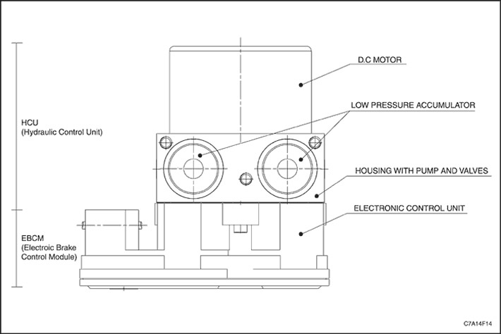
The hydraulic unit, together with the EBCM brake system controller attached to it, is located between the expansion tank and the bulkhead separating the engine compartment from the passenger compartment, on the left side of the vehicle.
The hydraulic unit mainly consists of shut-off valves, two electromagnetic valves for each wheel, a hydraulic pump, two accumulators. To prevent the wheels from locking, the hydraulic unit regulates the fluid pressure supplied to the brake mechanisms of the front and rear wheels.
Arrangement of functional blocks
Valve distribution
Only the shut-off valve and the electric selector valve (ESV) for the wheel being monitored are activated. When monitoring both wheels on one side of the vehicle, both shut-off valves/ESVs are activated. The shut-off valves must be permanently activated. Details of the valve timing during the pressure increase, hold and decrease stages are shown in the table.
|
|
Normally open valve
|
Normally closed valve
|
Shut-off valve
|
ESV valve
|
|
Pressure holding phase
|
Closed
|
Closed
|
Closed
|
Closed
|
|
Pressure increase phase
|
Cliff
|
Closed
|
Closed
|
Break (1)
|
|
Pressure reduction phase
|
Closed
|
Cliff
|
Closed
|
Closed
|
(1) The ESV valve of the controlled wheel shall open simultaneously with the normally open valve, but shall remain open for 14 ms longer than the normally open valve.
HECU (hydraulic block controller)
The HECU controller performs the following main functions:
to ensure effective braking and vehicle stability. In the DDRP system, the rear brake pressure maintaining solenoid valve is powered by the ignition system. The red brake warning lamp illuminates when the following faults occur.
- Monitors wheel speed sensor inputs.
- Detects the onset of wheel slip.
- Controls the braking system in anti-lock mode.
- Monitors the serviceability of the electrical elements of the system.
The HECU continuously monitors the speed of each wheel to determine when slippage begins. If a tendency to slip is detected at any of the wheels, the HECU commands the appropriate valves to change the brake fluid pressure in some or all of the hydraulic circuits, thereby eliminating wheel slippage and ensuring optimal braking. The HECU continues to monitor the pressure in the hydraulic circuits until the tendency to slip disappears. The HECU also continuously receives a signal from the steering angle sensor for optimal ABS operation. Therefore, "steering angle sensor centering" should be performed after replacing the HECU. If an error is detected, the HECU can disable the ABS and turn on the ABS warning lamp in the instrument cluster. The HECU also controls the display of diagnostic trouble codes when operating in diagnostic mode.
Solenoid valve relay
The solenoid valve relay supplies power to the pump motor and to the solenoid valves. The contact present in the relay is normally open, but is closed at the command received during initialization. This relay contact will remain closed for the remainder of the trip until any diagnostic fault code is stored in memory that requires this contact to be opened. If a diagnostic fault code is stored in memory that requires a command to turn off the relay, then the battery voltage supply to the pump motor and solenoid valves will stop for the rest of the trip and the ABS will not be able to function. The relay is an integral part of the HECU and is not separately serviced.
Wheel speed sensors and toothed rings
Each wheel has a wheel speed sensor. The sensors transmit wheel speed information to the HECU using small AC voltage signals. The signal is transmitted to the HECU using an interface, which can cause the HECU to receive false speed sensor signals, such as those caused by electromagnetic interference.
ABS warning light
The ABS indicator light is located in the instrument cluster and illuminates when the HECU detects a fault with the ABS. The ABS indicator light informs the driver that there is a fault that has caused the ABS to be switched off. If only the ABS indicator light is illuminated, braking can be performed normally, including the use of the brake booster.
The ABS warning light comes on in the following cases.
- ABS malfunction detected. As already noted, the ABS warning light comes on when a malfunction is detected in the ABS.
- Checking the instrument cluster bulb When the ignition is turned on, the ABS warning lamp lights up for approximately three seconds and then goes out.
Brake warning light
The red brake warning light is located in the instrument cluster and illuminates to warn the driver of a brake system fault that could cause poor brake performance. The light will illuminate when the parking brake is applied or not fully released, or if the brake fluid level sensor shorts out (when the brake fluid level in the master cylinder reservoir is too low). When the brake fluid level sensor is shorted (too low level) the brake warning light will remain on until the cause of the light is corrected. In addition, if there are some faults in the system, the light will also come on, letting the driver know that the DDRP system (separate dynamic distribution of brake forces on the rear wheels) disabled
Electronic Stability Program (ESP)
When this system operates, braking forces are applied to the appropriate wheels of the vehicle, which creates a moment that counteracts the yaw movement. This means that a certain pressure is applied to one or both wheels on the left side of the vehicle if the yaw movement is clockwise, and to the contours of the wheels on the right side of the vehicle if the yaw movement is counterclockwise.
When the brakes are applied during ESP operation, the pressure in the wheel circuits, in which normally open valves are closed to maintain zero pressure at the wheels, is raised to a level corresponding to the pressure in the brake master cylinder (TMC) by the EBCM, which opens the appropriate inlet valves (normally open) valves (electrical control of the braking system). The pressure level at the controlled wheels is also increased within physical limits to maintain the yaw moment despite the increase in brake pressure.
The brake pressure in the TMC cylinder causes a corresponding increase in the opening pressure of the shut-off valves (tMC cylinder pressure works to close the shut-off valves in which the pressure is not balanced). As a result, the pump raises the system pressure by the amount of TMC cylinder pressure, which can lead to unacceptably high pressure levels in the Hydraulic Control Unit (HCU) until appropriate countermeasures are taken.
For this reason, the EBCM opens the shut-off valves when the TMC cylinder pressure reaches 100 bar in order to limit the pressure. It is no longer possible to increase the pressure in the system further using the pump. The pressure for the ESP system is therefore supplied only by the TMC cylinder. As with the ABS/TCS, the pressure in the wheel circuits is changed by means of the inlet and outlet valves. During the pressure reduction phase of the working cycle, the ESV valves are closed so that the diverted brake fluid can be returned to the brake system from the low-pressure accumulators.
EBD (electronic Brakeforce Distribution)
The EBD system complements the effectiveness of the ABS system by controlling the slip of the rear wheels in the braking range, thus optimising the driving characteristics during braking. The braking force is close to the maximum braking force of the rear axle and is controlled electronically.
When the EBD system is entered, the pressure supply to the rear axle is cut off via the normally open valves when the slip of at least one rear wheel exceeds a preset limit. Depending on the actual wheel slip, this may be followed by additional signals to increase the pressure. The release valves are only used to reduce the pressure when a risk of locking is detected on the rear axle. As a rule, the control algorithm is aimed at achieving maximum use of braking force with minimum valve action (noise, pedal response). Since the diverted fluid volumes are usually very small, they can be stored in a low-pressure accumulator. The HCU pump is not required for the EBD system to operate. After the EBD control is completed, the brake fluid is diverted from the low-pressure accumulators to the brake fluid reservoir by briefly switching on the pump.
HBA (auxiliary hydraulic brake)
In the event of a very rapid increase in pressure in the master cylinder of the brake system, emergency braking mode is recognized and the hydraulic auxiliary brake (HBA) function is activated. The hydraulic pump and the shut-off valves of both hydraulic circuits are activated. The pressure on the wheels then becomes higher than the pressure of the master cylinder. The pressure compensation function provided in this HBA brake design ensures a certain increase in braking force by applying additional pressure during HBA operation instead of constantly orienting the system to the ABS. This compensation depends on the pressure gradient achieved during HBA operation, subject to the following rule: the faster the driver presses the brake, the more support, i.e. compensation, is provided to him.
If the tire pressure reaches the locking pressure, the normal ABS function controls the stability of the wheels by switching (normally open) inlet and (normally closed) exhaust valves. Thus, the activation of the HBA has the same effect as if the driver were braking with a large force on the pedal, sufficient to reach the locking pressure.
If the pedal force decreases significantly, the HBA function classifies this as the driver's intention to end full braking. Therefore, at the end of the HBA operation, the pressure between the wheel brakes and the master cylinder is equalized. This is achieved by intermittently opening the cut-off valves.
DSC (automatic hill descent control system)
The DSC system is a speed control system for off-road vehicles and is generally used on steep slopes. The system can only operate in first or reverse gear and with the accelerator pedal fully released. The programmed control speed is fixed and cannot be changed by the driver. Pressure control on all four wheels is carried out by actuating ESV valves, cut-off valves and a pump.