


Contents: Diagnostic Trouble Codes ↧ Checking the diagnostic circuit ↧ Checking the diagnostic circuit ↧ Diagnostic test drive ↧ Initialization sequence ↧
Diagnostic Trouble Codes
|
DTC
|
Description
|
|
C0035
|
Front Left Wheel Speed Sensor Circuit
|
|
C0040
|
Front Right Wheel Speed Sensor Circuit
|
|
C0045
|
Rear Left Wheel Speed Sensor Circuit
|
|
C0050
|
Rear Right Wheel Speed Sensor Circuit
|
|
C0110
|
electric fuel pump circuit
|
|
C0131
|
Anti-lock braking system (ABS) / traction control system (TCS) operating circuit
|
|
C0161
|
Anti-lock Brake System (ABS)/Traction Control System (TCS) Brake Switch/Sensor Circuit
|
|
C0186
|
Lateral acceleration accelerometer circuit
|
|
C0196
|
Yaw rate sensor circuit
|
|
C0252
|
Vehicle Stability Enhancement System (VSES) Sensors are uncorrelated
|
|
C0280
|
The stability enhancement system is running for too long
|
|
C0287
|
Longitudinal acceleration accelerometer circuit
|
|
C0292
|
VSES Instrument Cluster Sensor Circuits
|
|
C0460
|
Steering wheel position sensor
|
|
C0550
|
Controller (ECU) performance
|
|
C0551
|
Option configuration error
|
|
C0561
|
Saving information on system shutdown
|
|
C0569
|
System configuration error
|
|
C0899
|
Device {single or 1} Low Voltage
|
|
C0900
|
Device {single or 1} High Voltage
|
|
U0102
|
Lost connection with RDM (Transfer case module)
|
|
U1500
|
Communication fault on CAN bus 2 (sensor group) (The bus is disconnected)
|
|
U2100
|
CAN bus communication fault (The bus is disconnected)
|
|
U2105
|
Lost connection with ECM
|
|
U2106
|
Lost connection with gearbox controller
|
|
U2107
|
Lost connection with BCM
|
|
U2139
|
Connection to the gateway unit has been lost
|
|
U2142
|
Lost connection with sensor group
|
|
U2143
|
Lost connection with steering wheel angle sensor
|
Checking the diagnostic circuit
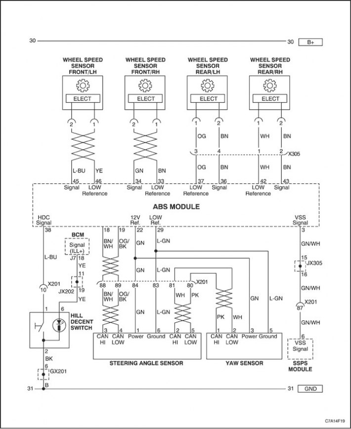
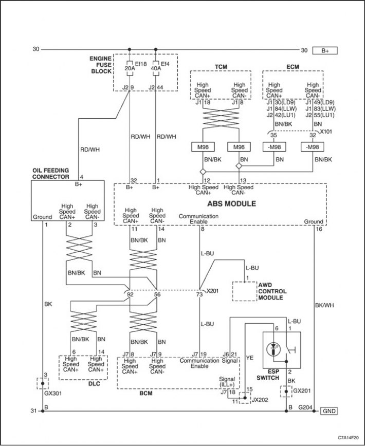
Description of the system
The diagnostic circuit test is a systematic method for finding the cause of malfunctions in the ABS/DDRP system.
A service technician troubleshooting any ABS/DDRP system malfunction should begin by checking the diagnostic circuits. The diagnostic circuits are organized in a logical sequence that the technician should follow when troubleshooting the cause of the malfunction.
For serial transmission/reception of data from the EBCM brake controller, contacts 11 and 14 are used. The constant supply voltage from the battery is supplied to the EBCM via contacts 1 and 32, and the voltage when the ignition is turned on is supplied to contact 4. The EBCM is connected to ground via contact 16.
Diagnostic procedure
When servicing the ABS/DDRP system, follow the steps below.
1. Check the condition of the mechanical elements of the vehicle structure related to the braking system.
- The brake fluid level in the reservoir is normal.
- Check visually whether the fluid in the master cylinder is contaminated
- Check the master cylinder and modulator for leaks.
- Check the master cylinder and modulator for leaks.
- Check the brake components on all wheels.
- Make sure that the brakes do not grab (adjusting the brake warning light switch).
- Check the equality of braking force on all wheels (no lateral drift)
- Check the brake pads for wear and damage.
- Check wheel bearings for wear and damage.
- Check the wheel speed sensors and their wires.
- Check the speed sensor toothed rings for damage.
- Check the tire for wear and determine the tread thickness.
- To verify that there is a malfunction, perform a test drive.
2. Perform a diagnostic circuit check and proceed to the appropriate troubleshooting table.
3. After all faults in the ABS system have been eliminated, the messages with the system fault codes should be erased.
Checking the diagnostic circuit
| Step | Operation | Values | Yes | No |
| 1 |
Does the scan tool communicate with the EBCM?
|
-
|
Jump to operations 2
|
Jump to operations 4
|
| 2 |
Are there any diagnostic trouble codes, current or historical?
|
-
|
Jump to operations 3
|
Jump to operations 7
|
| 3 |
|
-
|
-
|
-
|
| 4 |
Check the DLC connector wiring harness, battery and cable.
Are all positions ok?
|
-
|
Jump to operations 5
|
Jump to operations 6
|
| 5 |
Are any DTCs found?
|
-
|
Jump to operations 1
|
The system is normal
|
| 6 |
Are any DTCs found?
|
-
|
Jump to operations 1
|
The system is normal
|
| 7 |
Did the ABS warning light and brake warning light come on for 3 seconds? (checking lamps)?
|
-
|
Jump to operations 8
|
Jump to operations 9
|
| 8 |
The system is functioning normally.
|
-
|
The system is normal
|
-
|
| 9 |
Did the lamp continue to burn?
|
-
|
Jump to operations 10
|
The system is normal
|
| 10 |
Refer to the appropriate table for DTC troubleshooting instructions.
|
-
|
-
|
-
|
Diagnostic test drive
When servicing vehicles, the Anti-lock Braking System (ABS) and Traction Control System (TCS) require test drives to perform all tests and run all system functions. A test drive may also be required to reset individual trouble codes described in this section. Diagnostic System Check (including test drive) should be carried out after completion of vehicle repairs in order to check the effectiveness of the repair work performed.
The diagnostic test drive mode depends on the nature of the ABS/TCS problems.
1. Read the Diagnostic Instructions and Conditions for Setting the DTC.
2. Reconnect all previously disconnected components.
3. Start the engine.
4. Drive the vehicle for at least 10 minutes, observing the following conditions. No illegal or unsafe maneuvers are allowed while driving.
- Driving on the motorway
- Uneven roads
- Review customer complaints and re-create required driving conditions.
- Without disconnecting the engine, connect the scanning device and check for any DTCs. If any DTCs are installed, follow the instructions for removing these diagnostic trouble codes from the corresponding table.
Initialization sequence
The Electronic Brake Module (ECBM) performs an initialization routine at the beginning of each ignition cycle until the vehicle speed reaches 15 km/h (9 miles/hour). The initialization program sets the sequence of operation of each solenoid valve and pump motor, as well as the necessary relays, in order to check the operation of the components. If any DTC is detected, the Brake System Controller (EBCM) will set a specific fault code. The initialization sequence can be felt and heard, and this is a common part of the job.