


Contents: Removal procedure ↧ Installation procedure ↧
Warning! Brake fluid can irritate eyes and skin. If it gets into your eyes or on your skin, take the following steps:
- In case of contact with eyes, rinse with plenty of water.
- In case of contact with skin, wash with soap and water.
- If swallowed, seek medical attention immediately.
Note: Avoid spilling fluid on connections, wires and cables. Brake fluid will damage painted surfaces and cause corrosion of electrical components. If brake fluid comes into contact with painted surfaces, rinse the area immediately with water. If brake fluid comes into contact with electrical connections, wires or cables, wipe off the fluid with a clean cloth.
Removal procedure
1. Turn the ignition switch to the OFF position.
2. Remove the engine coolant reservoir and fuse box. See Section 1D2, Engine Cooling System (FAM II 2.4 D) and section 1E2 Engine Electrical System (FAM II 2.4 D).
3. Clean the area of the brake modulator assembly tube fittings from accumulated dirt and foreign materials.
4. Disconnect the electrical connector from the electronic brake control module (EBCM).
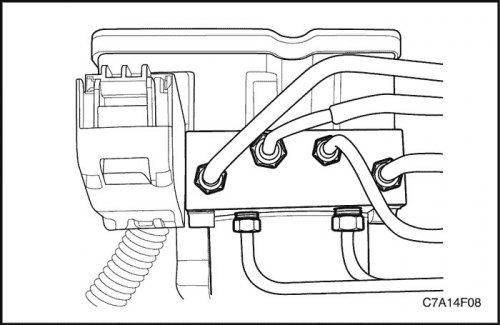
5. Place a towel under the brake modulator assembly to absorb any leaking brake fluid.
Important: Before disconnecting the brake lines from the Anti-lock Brake System (ABS) modulator assembly, record the location of the brake lines relative to the valve assembly to facilitate subsequent reassembly.
6. Disconnect the tube fitting nut from the brake pressure modulator valve (BPMV).
7. Cover the ends of the brake pipes to prevent fluid spillage and contamination of the environment.
8. Close the openings of the brake pipes of the modulator to prevent fluid spillage and contamination of the environment.
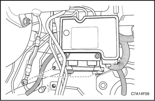
9. Unscrew the bolt and nuts of the bracket from the body panel.
10. Loosen the damping bolts securing the brake modulator assembly to the bracket.
Installation procedure
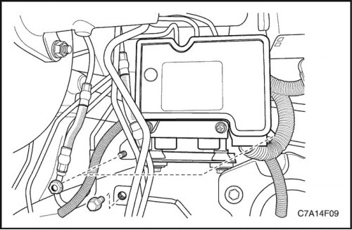
1. Install the damping mounting bolts on the brake modulator assembly.
Tighten
Tighten the brake modulator assembly damper bolts to 11 N·m (8 lb-ft).
2. Install the brake modulator assembly onto the bracket.
3. Install the brake modulator assembly with the bracket attached to the body panel.
Tighten
Tighten the bracket mounting bolts and nuts to 10 N·m (89 lb-in).
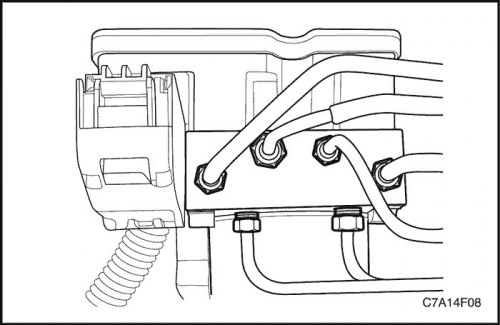
4. Remove the caps from the ends of the master cylinder pipes.
5. Remove the plugs from the master cylinder holes on the modulator assembly.
6. Connect the master cylinder pipes to the modulator assembly in the same location where they were removed.
7. Tighten the brake pipe fitting nuts.
Tighten
Tighten the fitting nuts to 16 N·m (12 lb-ft).
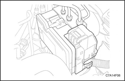
8. Connect the electrical connector to the electronic brake control module (EBCM).
9. Install the engine coolant reservoir and fuse box.
10. Bleed the hydraulic brake system. See Part 4A. Hydraulic brakes.
11. Turn the ignition switch to the ON position. DO NOT start the engine.
12. Perform a diagnostic circuit check in this section.
(The original source of the article is the website: «CHEVYMAN.RU»)