


Contents: Disassembly procedure ↧ Assembly procedure ↧
Disassembly procedure
1. Remove the generator. Follow the step "Generator" Car maintenance in this section.
2. Make markings on the end face to facilitate subsequent assembly.
3. Remove the plastic cover with a lever, releasing the stator connectors.
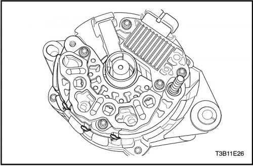
Note: If the starter connectors are not welded, melt the wires. Avoid excessive heat, this can damage the diodes in the bridge rectifier.
4. Remove the stator connectors from the bridge rectifier by cutting the wires.
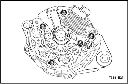
5. Remove the partition with a lever.
6. Remove the rectifier/regulator/brush holder screws.
7. Remove the brush holder and regulator.
Important: If the brush can be reused, reassemble the brush with the holder using the locking pin, after cleaning it with a soft cloth.
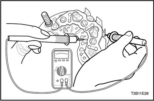
8. Check the bridge rectifier by connecting the ohmmeter leads to the rectifier and heat sink.
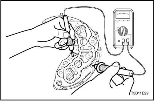
9. Check again by connecting the ohmmeter leads in reverse order.
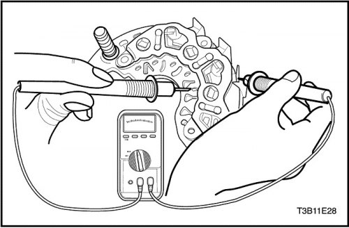
10. Replace the bridge rectifier if the readings are the same.
11. Check the two remaining diodes after the above procedure.
Note: Some types of ohmmeters are not suitable for testing bridge diodes. In this case, consult the manufacturer for capacitance testing.
12. Check the diodes by connecting the ohmmeter leads to the rectifier and support plate connectors. Replace the bridge rectifier if the readings are the same.
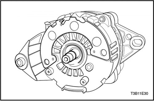
13. Remove the generator through-bolts.
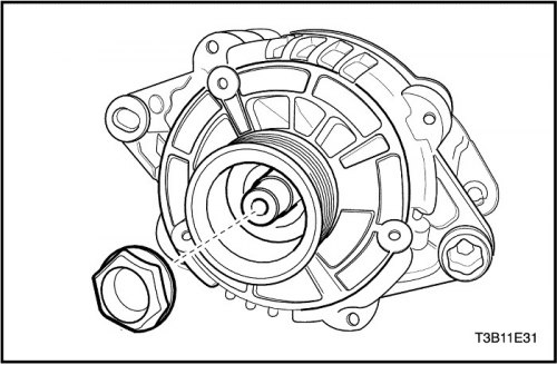
Important: The tightening torque for this nut is 81Nm (60 lb-ft), the nut cannot normally be loosened by hand.
14. Remove the bearing nut at the drive end of the generator.
15. Remove the pulleys and flanges.
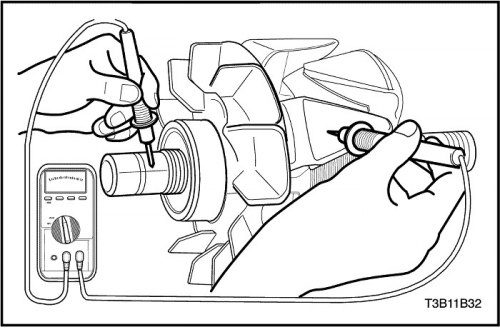
16. Check the rotor for an open circuit using an ohmmeter on the drive end piece. The reading should be high enough, otherwise replace the rotor.
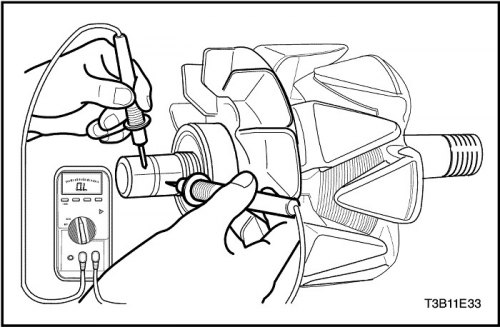
17. Check the rotor for open circuit and short circuit. The reading should be between 1.7 and 2.3 ohms, otherwise the rotor must be replaced.
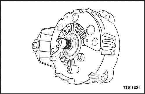
18. Remove the end piece from the shaft.
19. On vehicles with an internal alternator fan, remove the end piece and fan.
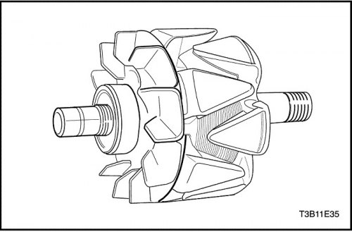
20. Remove the rotor.
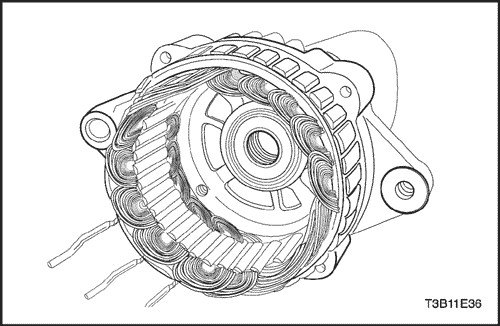
21. Remove the stator.
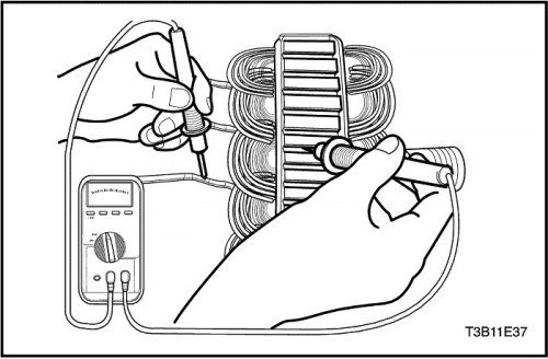
22. Check the stator for open circuit using an ohmmeter.
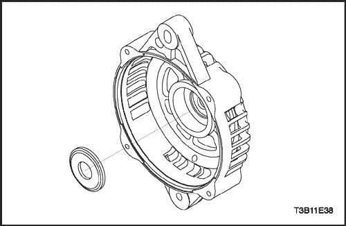
23. Remove the ring on the end piece from the contact ring side.
Assembly procedure
1. Install the new ring into the end piece on the contact ring side.
2. Install the stator.
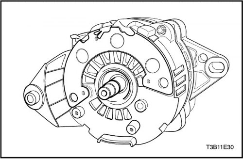
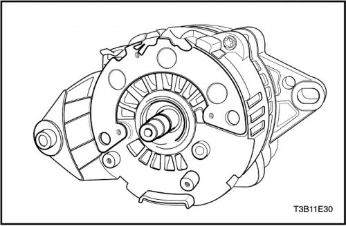
3. Install the rotor shaft with the end piece into the slip ring assembly so that the gap between the outer race and the end piece frame is 1.9 mm (0.075 in.).
4.. Install the generator through screws.
Tighten
Tighten the generator through bolts to 10 Nm (89 lbs.in).
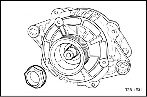
5. Install the fan, flanges and pulley on the rotor shaft and secure them with the nut.
Tighten
Tighten the generator drive side bearing nut to 81 N·m (60 ft·lbs).
6. Install the generator. Follow the step "Generator" Car maintenance in this section.
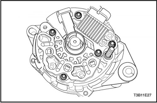
7. Weld the brush holder terminal to the regulator terminal if it was removed.
8. Secure the brush holder with the locking pin and weld the regulator/brush holder terminal to the rectifier terminal.
9. Apply silicone grease between the bridge rectifier and the end piece to dissipate heat.
10. Tighten the screws holding the rectifier regulator/brush holder to the end piece.
11. Use a pin to drive the protective cover into the brush.
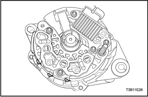
Note: Take precautions to protect the vehicle by protecting the bridge rectifier diode from exposure to excessive heat during welding.
12. Weld the bridge rectifier connectors.