


Contents: Removal procedure ↧ Installation procedure ↧
Removal procedure
1. Disconnect the negative battery cable.
2. Disconnect the intake air temperature (IAT) sensor connector.
3. Remove the air cleaner assembly. See Section 1C1, Engine Mechanical - FAM II 2.4D.
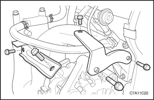
4. Disconnect the wiring harness connector from the generator.
5. Remove the generator upper bracket mounting screws and the clamp screws that connect the generator to the intake manifold.
6. Raise and secure the vehicle.
7. Remove the flexing accessory drive belt. See section 1C1, Engine Mechanical Part - FAM II 2.4D.
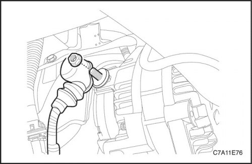
8. Disconnect the wire from the generator that connects the generator wire to the starter.
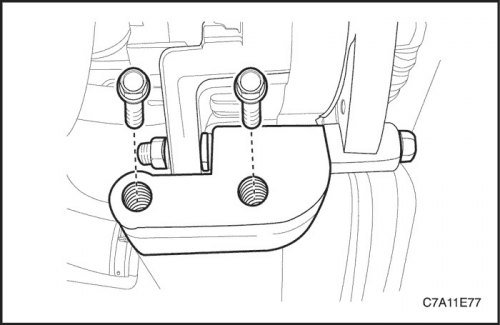
Note: Do not remove the generator through-bolt, nut and washers at this stage.
9. Remove the nut and release the washers holding the screw that secures the lower generator bracket to the generator.
10. Remove the generator lower support bracket screws.
11. Carefully remove the generator with the lower support bracket.
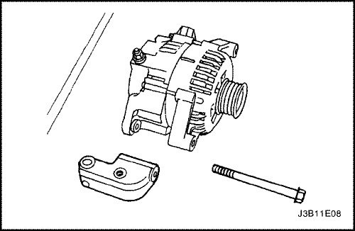
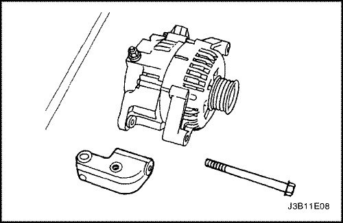
12. Remove the through screw, nut and washer connecting the generator to the lower support bracket.
Installation procedure
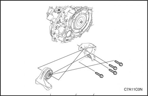
1. Install the lower generator support bracket onto the generator and insert the through screw.
Note: Do not tighten the generator through-bolt at this stage.
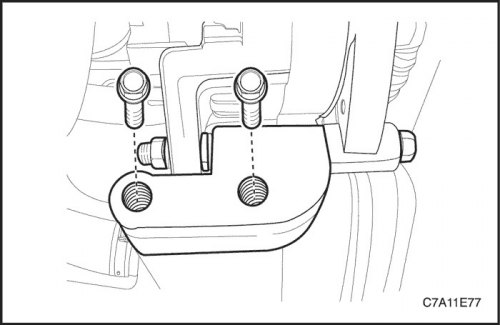
2. Install the generator and the assembled lower support bracket on the engine block.
Tighten
Tighten the alternator lower support bracket screws to 25 Nm (18 ft·lbs).
3. Tighten the through screw connecting the generator to the lower support bracket.
Tighten
Tighten the alternator through bolt to 40 Nm (30 ft·lbs).
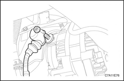
4. Connect the wire from the end of the generator to the starter to the generator.
5. Install the flexing accessory drive belt. See section 1C1, Engine Mechanical Part - FAM II 2.4D.
6. Lower the car.
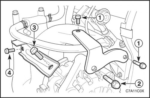
7. Install the upper generator bracket and the clamp connecting the generator to the intake manifold.
8. Install the generator upper bracket mounting screws and the generator to intake manifold clamp screws.
Tighten
Tighten the locking screws (1) of the upper generator bracket to 25 Nm (18 ft·lbs), and screw (2) up to 35 Nm (26 ft·lbs).
Tighten the locking screw (3) of the clamp connecting the generator to the intake manifold to 35 Nm (26 ft·lbs), and screw (4) up to 25 Nm (18 ft·lbs).
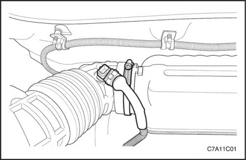
9. Connect the wiring harness connector to the generator.
10. Install the air cleaner assembly and the intake air temperature sensor connector. See section 1C1, Engine Mechanical Part - FAM II 2.4D.
11. Connect the negative battery cable.
[The text of the article was obtained from the website chevyman]