


Contents: Removal procedure ↧ Installation procedure ↧
Removal procedure
Cylinder Bank 1 - Sensor 1
1. Disconnect the negative battery cable.
Note: The oxygen sensor has a non-detachable flexible lead and connector. Do not remove the flexible lead from the oxygen sensor. Damage to or removal of the flexible lead or connector will affect the operation of the oxygen sensor. Handle the oxygen sensor with care. Do not drop the oxygen sensor.
2. Disconnect the upper heated oxygen sensor connector at the rear of the cylinder head of cylinder bank 1.
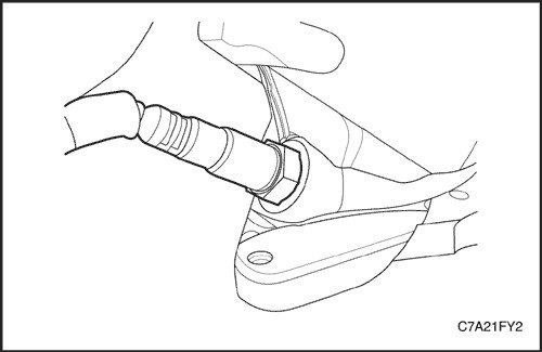
3. Remove the front exhaust pipe. See Part 1G3, Exhaust System - HFV6 3.2L.
4. Remove the rear catalytic converter. See Part 1G3, Exhaust System - HFV6 3.2L.
5. Remove the rear exhaust manifold. See Part 1C2, "Engine Mechanical - HFV6 3.2L".
Caution! Cool the engine before removing the oxygen sensor. Removing the oxygen sensor on a hot engine may damage the threads in the exhaust manifold.
6. Using the DW170-010 Oxygen Sensor Remover/Installer, carefully remove the upper heated oxygen sensor from the rear exhaust manifold.
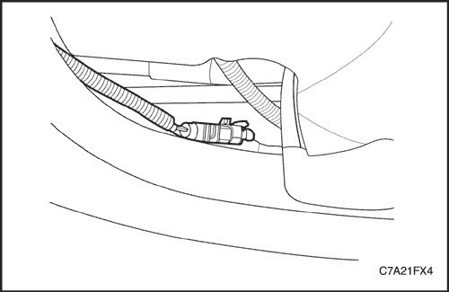
Cylinder Bank 1 - Sensor 2
1. Disconnect the negative battery cable.
2. Disconnect the lower heated oxygen sensor connector.
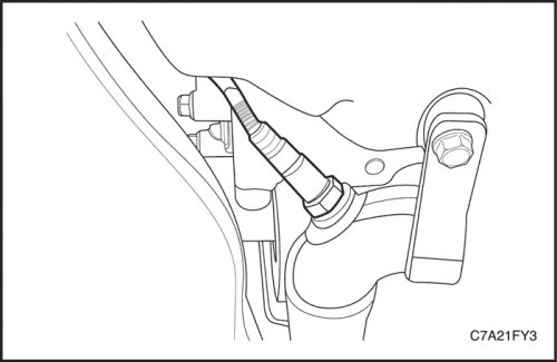
Caution! Cool the engine before removing the oxygen sensor. Removing the oxygen sensor on a hot engine may damage the threads in the exhaust manifold.
3. Using the DW170-010 Oxygen Sensor Remover/Installer, carefully remove the lower heated oxygen sensor from the exhaust downpipe.
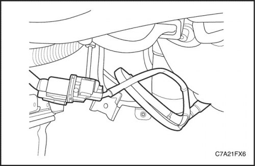
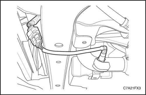
Cylinder Bank 2 - Sensor 1
1. Disconnect the negative battery cable.
2. Disconnect the upper oxygen sensor connector.
Caution! Cool the engine before removing the oxygen sensor. Removing the oxygen sensor on a hot engine may damage the threads in the exhaust manifold.
3. Using the DW170-010 Oxygen Sensor Remover/Installer, carefully remove the upper heated oxygen sensor from the front exhaust manifold.
Cylinder Bank 2 - Sensor 2
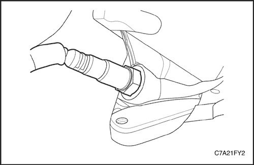
1. Disconnect the negative battery cable.
2. Disconnect the lower heated oxygen sensor connector.
Caution! Cool the engine before removing the oxygen sensor. Removing the oxygen sensor on a hot engine may damage the threads in the exhaust manifold.
3. Remove the lower heated oxygen sensor from the exhaust downpipe.
Installation procedure
Important: A special anti-seize compound is used on the oxygen sensor threads. This compound consists of liquid graphite and glass beads. The graphite burns out, but the glass beads remain and make it easier to remove the sensor. New or repaired sensors already have the compound applied to the threads. If the sensor is removed from the engine or reinstalled, then it is imperative to apply the anti-seize compound to the threads before reinstalling.
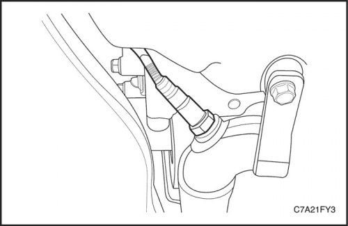
Cylinder Bank 1 - Sensor 1
1. If necessary, coat the heated oxygen sensor threads with anti-seize lubricant.
2. Using the Oxygen Sensor Remover/Installer DW170-010, carefully install the upper heated oxygen sensor to the rear exhaust manifold. Do not remove the flexible lead from the oxygen sensor. Damage to or removal of the flexible lead or connector will affect the operation of the oxygen sensor. Handle the oxygen sensor with care. Do not drop the oxygen sensor.
Tighten
Tighten the heated oxygen sensor to 50 N·m (37 lb-ft).
Cylinder Bank 1 - Sensor 2
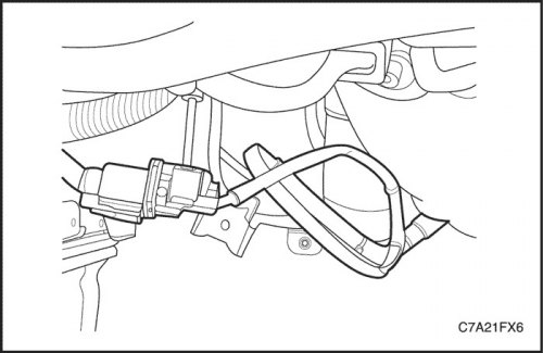
1. If necessary, coat the heated oxygen sensor threads with anti-seize lubricant.
2. Using the DW170-010 Oxygen Sensor Remover/Installer, install the lower heated oxygen sensor onto the exhaust downpipe.
Tighten
Tighten the heated oxygen sensor to 50 N·m (37 lb-ft).
3. Connect the upper heated oxygen sensor connector.
4. Connect the negative battery cable.
Cylinder Bank 2 - Sensor 1
1. If necessary, coat the heated oxygen sensor threads with anti-seize lubricant.
2. Using the DW170-010 Oxygen Sensor Remover/Installer, carefully install the upper heated oxygen sensor onto the front exhaust manifold.
Tighten
Tighten the heated oxygen sensor to 50 N·m (37 lb-ft).
3. Connect the upper heated oxygen sensor connector.
4. Connect the negative battery cable.
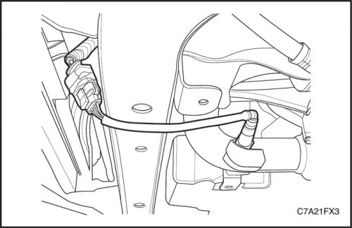
Cylinder Bank 2 - Sensor 2
1. If necessary, coat the heated oxygen sensor threads with anti-seize lubricant.
2. Using the DW170-010 Oxygen Sensor Remover/Installer, install the lower heated oxygen sensor onto the exhaust downpipe.
Tighten
Tighten the heated oxygen sensor to 50 N·m (37 lb-ft).
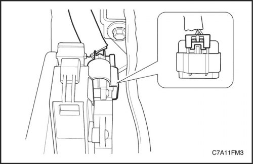
3. Connect the lower heated oxygen sensor connector.
4. Connect the negative battery cable.
[Information taken from the official website: ChevyMan]