


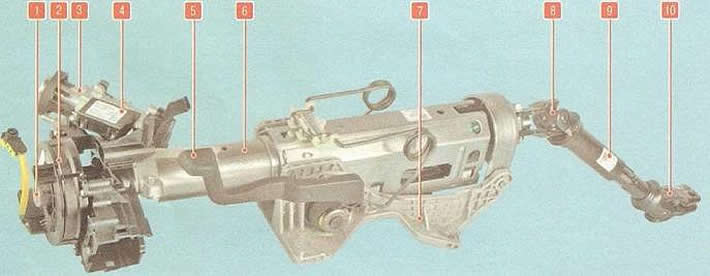
Fig. 8.1. Steering column: 1 - steering column shaft; 2 - contact ring of horn and airbag; 3 - ignition switch (lock); 4 - immobilizer controller; 5 - steering column adjustment mechanism lever; 6 - steering column housing; 7 - steering column bracket; 8, 10 - cardan joints of the intermediate shaft; 9 - intermediate shaft
Steering wheel with driver's airbag, horn switch installed in the central pad of the steering wheel. Steering wheel hub is bolted to the steering column shaft.
The steering column (Fig. 8.1) is trauma-safe, height-adjustable, and equipped with an anti-theft device in the ignition switch that locks the steering wheel shaft. The intermediate shaft is connected to the steering shaft by a cardan joint.
The steering gear (Fig. 8.2) is installed in the engine compartment. The steering gear housing is secured to the front suspension subframe.
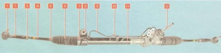
Fig. 8.2. Steering mechanism: 1 - ball joint of the steering rod end; 2 - steering rod end; 3 - Tie rod end lock nut; 4 - steering rod; 5, 7 - cover clamps; 6 - protective cover; 8 - bracket for fastening the steering column to the subframe; 9, 10 - pipelines; 11 - steering gear housing; 12 - steering gear shaft
The pressure of the working fluid in the power steering is created by a vane-type pump, which is mounted on the engine bracket and driven by a poly V-belt from the crankshaft pulley. The bypass valve installed in the pump maintains the required pressure of the working fluid in the power steering depending on the engine crankshaft speed. The power steering reservoir is installed in the engine compartment on the right side and is connected by hoses to the power steering pump and to the working fluid return line. If the power steering fails, the ability to control the car is retained, but the force on the steering wheel increases.
The steering rods are attached to the steering rack with ball joints. The steering rod ends are attached to the steering knuckles of the front suspension with ball joints. The steering rod is secured with a nut to prevent it from turning in the end. The toe-in of the steered wheels is adjusted by rotating the steering rod in the ball joint relative to the end.