


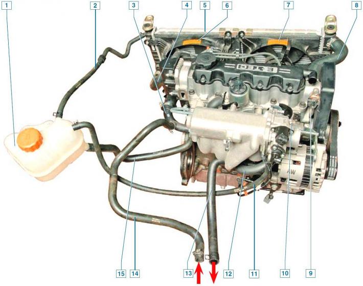
Cooling system: 1 - expansion tank; 2 - radiator steam outlet hose; 3 - supply pipe of the cooling system pump; 4 - radiator drain hose; 5 — cooling system radiator; 6 — fan casing; 7 — additional fan casing (only on vehicles with air conditioning); 8 — radiator supply hose; 9 — cylinder head outlet pipe; 10 — coolant temperature gauge sensor; 11 — hose for draining liquid from the throttle body heating unit; 12 - bypass hose; 13 — heater supply hose; 14 — heater outlet hose; 15 — expansion tank filler hose
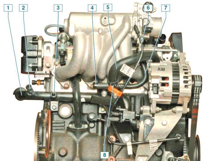
Cooling system components located on the rear of the engine: 1 - Cooling system pump supply pipe; 2 — expansion tank filler hose branch pipe; 3 — heater outlet hose branch pipe; 4 — heater supply hose branch pipe; 5 - bypass hose; 6 — branch pipe of the hose for draining liquid from the throttle assembly heating unit; 7 — hose for supplying liquid to the throttle assembly heating unit; 8 - tee
The cooling system is liquid, closed type, with forced circulation.
Consists of an expansion tank, coolant pump, engine cooling jacket, thermostat, connecting hoses and a radiator with an electric fan.
The heater radiator is connected to the cooling system.
The system is filled with coolant through the neck of the expansion tank.
The expansion tank is made of translucent plastic, which allows you to visually control the coolant level.
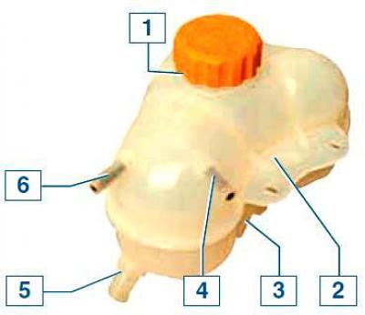
Expansion tank elements: 1 - filler cap; 2 - Upper bracket for mounting the tank; 3 — lower bracket for mounting the tank; 4 — radiator steam outlet hose branch pipe; 5 — inlet hose pipe; 6 — branch pipe of the hose for draining liquid from the throttle assembly heating unit
On the wall of the expansion tank there are MAX and MIN marks, between which the fluid level should be on a cold engine.
A steam outlet hose is connected to the upper left pipe of the tank, connecting the tank to the radiator, and a hose for draining liquid from the throttle assembly heating unit is connected to the upper right pipe.
The lower branch pipe of the tank is connected by a filling hose to the pump supply pipe.
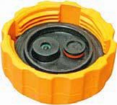
The tightness of the cooling system is ensured by the inlet and outlet valves in the expansion tank cap.
Replacing the expansion tank cap with a cap without valves, even if it is the right size and thread, will lead to an unacceptable increase in pressure in the cooling system (on a hot engine) and, as a consequence, to a leak of coolant at the connections of the hoses with the pipes.
The circulation of liquid in the cooling system is provided by the coolant pump.
The coolant pump is a vane, centrifugal type, driven by a toothed timing belt.
The fluid enters the pump through the supply pipe located on the rear wall of the cylinder block under the intake manifold.
From the pump, liquid under pressure is supplied to the engine cooling jacket, and from there to the outlet pipe of the cylinder head, under which the thermostat is located.
When the engine is not warmed up, the thermostat valve is closed and blocks the outlet pipe leading to the radiator of the cooling system.
In this case, all the liquid from the cylinder head through the bypass hose (put on the intake manifold pipe) enters the tee, and from there - into the heater radiator and the throttle assembly heating unit, bypassing the cooling system radiator, and then returns to the pump - a small circulation circle.
As the engine warms up, at a fluid temperature of 87°C, the thermostat valve begins to move, opening the outlet pipe of the cylinder head and allowing the flow of fluid into the radiator of the cooling system.
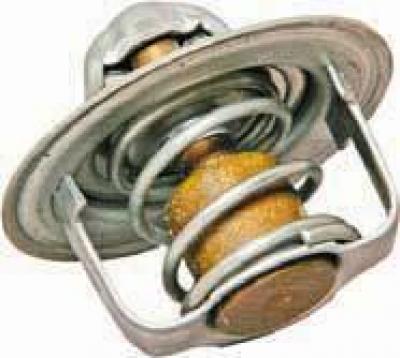
Thermostat
At a temperature of 102°C, the thermostat valve opens completely and the liquid enters the radiator of the cooling system, where it gives off heat to the surrounding air.
The movement of liquid through the engine cooling jacket and the radiator of the cooling system forms a large circulation circle.
The liquid circulates continuously through the throttle assembly heating unit and the heater radiator and does not depend on the position of the thermostat valve.
The radiator of the cooling system consists of two vertically located plastic tanks connected by aluminum tubes with cooling plates located in one row.
The liquid enters the radiator through the branch pipe of the right tank and is discharged through the branch pipe of the left tank.
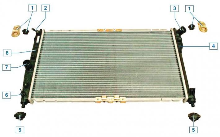
Radiator: 1 - bracket with upper mounting pad; 2 — steam outlet pipe; 3 — supply pipe; 4 - right tank; 5 - rubber cushion of the lower mount; 6 - drain plug; 7 — outlet pipe; 8 - left tank
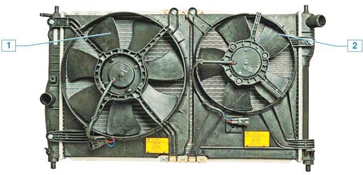
Cooling system fans: 1 - main fan; 2 - additional fan (car with air conditioning system)
There is a drain hole for removing the coolant.
The electric fan is installed in the casing behind the radiator.
On cars with air conditioning, two fans are installed - the main one (larger size) and additional.
The work of the main and additional (if available) the fans are controlled by an electronic control unit (ECU) of the engine, which, through the corresponding relay, ensures the rotation of the fan impeller at two speeds.
The ECU turns on the main fan at low speed when the coolant temperature is 93°C, at high speed at 97°C, switches the fan from high speed to low at 94°C and turns it off at 90°C.
The additional fan is switched on by the ECU at low speed when the air conditioning system is switched on, and at high speed when the coolant temperature reaches 97°C or the pressure in the air conditioner discharge line reaches 1882 kPa.
The coolant temperature gauge sensor is installed on the intake manifold on the right side in the direction of vehicle travel (see Removal the coolant temperature gauge sensor.
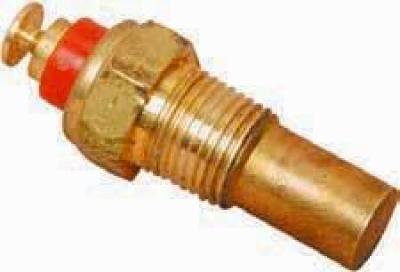
Coolant Temperature Gauge Sensor
The sensor sends information to the temperature gauge in the instrument cluster.