


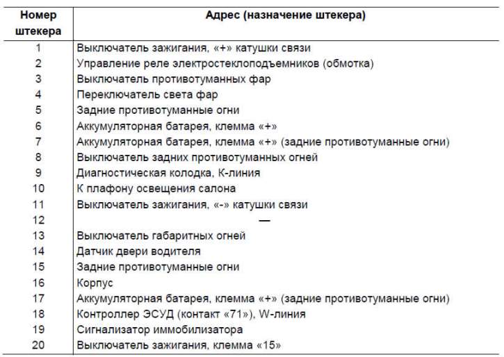
The composition of the immobilizer is shown in Figure 7-47. The immobilizer connection diagram is shown in Figure 7-48. The addresses of the output plugs of the APS-6 control unit are given in Table 7-15.
The immobilizer consists of a control unit 1, a system status indicator 3, located in the control lamp unit 2 (in the instrument cluster on vehicles with trim levels 55, 34), communication coil 5, structurally located in ignition switch 4, working code key 6 with container 7 of black color, training code key 8 with container of red color and the corresponding part of the engine control system controller program.
The operating modes and states of the APS are displayed using a signaling device and a buzzer inside the APS control unit.
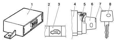
Figure 7-47. Composition of the immobilizer:
1 - control unit;
2 - control lamp block (instrument cluster on vehicles with trim level 55);
3 - immobilizer alarm;
4 - ignition switch;
5 - coupling coil;
6 - working ignition key;
7 - container with transponder (black - for working key, red - for training key);
8 - training ignition key.
The controller and control unit can be in one of two states:
- with the immobilization function turned off ("clean"). In this state, the controller and the APS control unit do not constitute a single system, and engine starting is permitted regardless of the APS;
- with the immobilization function enabled ("trained"). In this state, engine operation is possible only when the ECM receives the correct password from the APS control unit, issued when reading the corresponding code from the ignition key.
The controller and the APS control unit enter the trained state after the procedure of training the working ignition keys, performed using the training key. You can train either "clean" keys, i.e. those that have never been trained before, or those that have already worked with this particular APS.
After the training procedure is completed, the training key that was used to perform it becomes "its own" for this controller-APS control unit pair and it is recommended to use it only for performing training procedures.
Attention: The training key cannot be used to train any other APS control unit - ECM controller pair.
After training, the working ignition key is used to remove the engine start prohibition.
Attention. To ensure stable reading of the key code by the immobilizer, it is not allowed to attach two or more ignition code keys to one ring.
Immobilizer training
1. Close all doors. Insert the learning key into the ignition switch. Turn on the ignition, after 6 seconds the immobilizer indicator should light up with a constant light, displaying the unlearned state of the APS (if the APS has already been trained before, the alarm will not light up).
2. Turn off the ignition. The indicator should flash 5 times per second.
3. Within 6 seconds after the flashing starts, remove the training key and turn on the ignition with the working key. The APS control unit buzzer should emit 3 beeps. If this does not happen and the flashing stops, this means:
- the 6 second time interval was exceeded - repeat the training procedure, starting from step 1;
- the working key has already been trained with another APS or it is faulty - replace the working key and repeat the training procedure, starting from step 1.
4. After 3 beeps, wait 6 seconds until the APS control unit buzzer beeps 2 more times, and turn off the ignition.
5. Within 6 seconds, while the indicator continues to flash, remove the working key and turn on the ignition with the training key. The buzzer should emit 3 beeps and after 6 seconds another 2 beeps.
6. Turn off the ignition without removing the training key. The buzzer should emit a single beep and the indicator should flash at double the frequency (10 times per second).
The time between the moment the ignition is turned off and the indicator switches to accelerated flashing mode should not exceed 15 seconds.
If the sound signal does not sound and the indicator stops flashing, you should repeat the learning procedure again.
7. After the buzzer gives a single beep, no later than 10 seconds later, turn on the ignition. The buzzer should give 3 beeps (additionally, on vehicles with trim levels 55 and 34, equipped with a remote control and electrical package, the direction indicators should flash three times). After the buzzer sounds three times, turn off the ignition.
Attention. When performing step 7 after turning on the ignition, the process of storing codes by the ECM and the APS control unit begins, therefore it is strictly forbidden to turn off the ignition until three beeps have sounded. To ensure that the process of storing codes is completed, the time between turning on and turning off the ignition must be at least 5 seconds. Failure to comply with the above conditions may lead to blocking the ECM.
8. Remove the learning key. Wait with the ignition off for at least 10 seconds.
Check the immobilizer operation. To do this, turn on the ignition with a working key, the immobilizer indicator should not blink or light continuously. Perform a test start of the engine. If the engine starts, the learning procedure is complete, the system is in good working order.
Attention! If for any reason the training procedure was interrupted after performing step 4, it must be repeated and completed without changing the system components (ECU controller, immobilizer, code keys). If one of the system components, after an unfinished training process on one vehicle, is trained on another vehicle with different components, then software failures in its operation are possible.
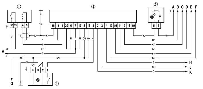
Figure 7-48. Immobilizer connection diagram:
1 - ignition switch;
2 - immobilizer;
3 - control lamp block (instrument cluster on vehicles with trim level 55);
4 - rear fog light switch;
A - to power sources;
B - to the controller, contact "71";
C - to the diagnostic socket;
D - to the driver's door sensor;
E - to the interior light;
F - to the outdoor lighting switch (turning on the parking lights);
G - to the fog lamps in the rear lights;
H - to the outdoor lighting switch (turning on low beam headlights);
J - to the fog light switch;
K - to the electric window relay (terminal "85").
Table 7-15. Addresses of the output plugs of the APS-6 control unit
Additional functions of the immobilizer
Rear fog light (RFL) on/off control
The ZPTO is switched on by pressing the ZPTO switch button if the low beam headlights or fog lights were previously switched on.
The ZPTO is switched off by pressing the ZPTO switch key again.
Automatic switching off of the ZPTO occurs when the low beam headlights and fog lights are switched off.
The indicator light located on the switch key will remain on throughout the entire operation of the ZPTO.
Issuing a warning about the key left in the ignition switch
If the ignition is off, the buzzer will sound an intermittent sound when the driver's door is opened if the key is left in the ignition switch.
Issuing a warning about left-on parking lights
If the ignition is off and the key is removed from the ignition switch, then when the driver's door is opened, the buzzer emits two intermittent beeps if the parking lights are on.
Electric window relay control
The electric windows can be controlled when the ignition is on or for 30 seconds after the ignition is turned off if the driver's door has not been opened.
Interior light switch-off delay control
This function allows you to keep the interior lighting on for some time after the driver's door is closed (all doors in configurations 55 and 34). The modes described below are implemented if the interior light switch is in the "off" position.
The lamp lights up when any door is opened, regardless of the position of the key in the ignition switch.
If the ignition is off, then after closing the driver's door with the other doors closed (the last door of the car in trim levels 55 and 34) the lamp continues to burn for 12 seconds and then gradually goes out over 2 seconds.
If during the delay in turning off the ceiling light (doors closed, ignition key in the "off" position) the ignition key is turned to the "on" position, the ceiling light will smoothly go out within 2 seconds, starting from the moment the ignition is turned on.
Description of diagnostics and repair of the immobilizer is given in the engine management system repair manual.