


Contents: Removal ↧ Installation ↧
Removal
1. Disconnect the cable from the negative terminal of the battery.
2. Loosen the front wheel nuts, raise the front of the vehicle and securely support it on struts. Set the vehicle's parking brake and block the rear wheels to prevent the vehicle from rolling off the stands. Remove both front wheels.
3. Pull back the protective boot at the bottom of the steering column to expose the steering column connection flange. Mark the steering column flange and shaft (see illustration).
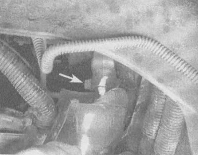
17.3. Scratch or paint a mark on the connection between the intermediate shaft and the steering gear shaft, then loosen the pinch bolt (indicated by the arrow)
4. Loosen the tension bolt (see illustration 17.3).
5. Remove the tie rod ends (see section 16).
6. Support the rear of the subframe with a jack and remove the rear bolts; loosen the front subframe bolts and lower the rear approximately 5 inches (see chapter 2, part 2.3, section 5).
7. Remove the heat shield from the steering gear (see illustration).
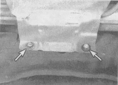
17.7. Unscrew the bolts (indicated by arrows) and remove the heat shield
8. Remove the tube clamp from the steering gear (see illustration).
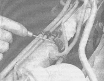
17.8 To remove the tube clamp from the steering gear, place the blade of a small screwdriver here and press the clamp upwards (the engine, gearbox and steering gear subframe have been removed from the vehicle)
9. Place the drain pan under the vehicle, positioning it under the steering gear. Using a socket wrench, disconnect the supply and drain lines (see illustration) from the steering gear. To prevent loss of hydraulic fluid, plug the lines.
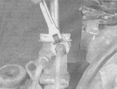
17.9 Use a spanner to loosen the threaded pipes from the steering gear
10. Unscrew the bolts and nuts (see illustrations).
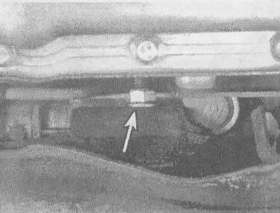
17.10a. Left steering gear mounting bolt (from the driver's side) and a nut (indicated by an arrow) |
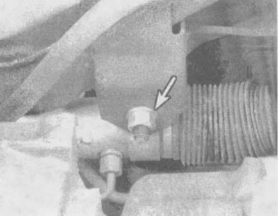
17.10b. Right (from the passenger side) steering gear mounting bolt and nut (indicated by the arrow) |
11. Remove the steering gear from its mountings, then move it forward and remove the pinch bolt.
12. Support the steering gear and carefully remove the entire assembly through the opening on the left side.
Installation
13. Installation is carried out in reverse order (see illustration).
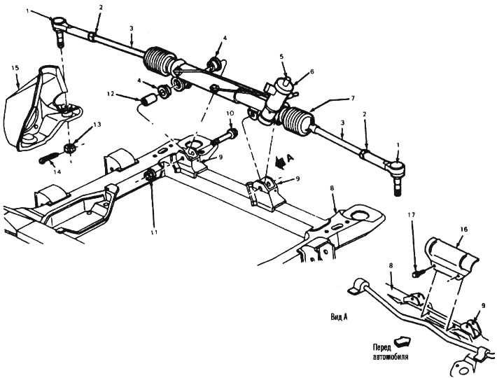
17.13. Steering unit parts: 1 - tie rod end, 2 - lock nut, 3 - tie rod, 4 - bushing, 5 - shaft, 6 - steering gear, 7 - protective cover, 8 - frame, 9 - steering gear mount, 10 - bolt, 11 - nut, 12 - bushing, 13 - castle nut, 14 - cotter pin, 15 - steering knuckle, 16 - heat shield, 17 - bolt
14. Insert the steering gear through the hole in the left mudguard and place it in place on the mounts. Install the bolts and nuts and tighten them to the torque specified in technical conditions of this chapter.
15. Connect the supply and drain pipes to the steering gear. Connect the tube clamp and install the heat shield.
16. Raise the subframe into place and tighten the bolts. Tighten the subframe bolts to the torque specified in technical data chapter 2, part 2.3.
17. Connect the tie rod ends to the rods or steering knuckles and tighten the nuts to the torque specified in the technical data at the beginning of the chapter. Insert new cotter pins.
18. Center the steering gear by aligning the previously applied marks. Install and tighten the tie bolt securely.
19. Install the front wheels, lower the vehicle and tighten the wheel nuts to the torque specified in technical conditions of chapter 1.
20. Connect the cable to the negative terminal of the battery.
21. Fill the power steering pump with the recommended type of hydraulic fluid and bleed the system (see section 20) and recheck the fluid level in the system. Check for leaks.
22. Check the front wheel alignment angles.
[The original article can be found on the resource chevyman.ru]