
Contents: Removal ↧ Installation ↧
Warning 1. Please read the following instructions carefully to familiarize yourself with the necessary operations before starting work. In addition, you will have to remove the gearbox, steering gear and lower control arms, as they all attach to the subframe, which must be removed as a single unit. This operation can only be performed safely by placing supports under the engine block and transmission, steering gear and subframe, disconnecting this assembly from the vehicle and raising the vehicle high enough to fully expose the entire assembly. Therefore, it is not recommended to perform this work without a car lift. Using any other method to lift the vehicle to gain access to the engine may result in serious damage to the vehicle or serious injury if the vehicle falls.
Warning 2: Gasoline is highly flammable, so take extra safety precautions before disconnecting any part of the fuel system.
Warning 3: The air conditioning system is under high pressure. Before disconnecting any hoses or fittings from the system, the pressure must be relieved at a service station.
Note: On models equipped with the Delco Loc II audio system, the immobilizer system must be disengaged before performing any operation that involves disconnecting the battery.
Removal
1. Relieve the fuel pressure in the system (see chapter 4, section 2) and disconnect the battery.
2. Close the fenders and hood. It is often convenient to remove the hood to increase the working space (see chapter 11, section 9). But since you are going to lower the engine (and not raise it), removing the hood in this case makes no sense.
3. Remove the air filter (see chapter 4, section 8).
4. To ensure proper assembly, label all vacuum lines, exhaust hoses, electrical connectors, ground buses, and fuel lines. Pieces of sticky tape with numbers or letters written on them will help you avoid confusion during assembly (see illustration). Also, draw a diagram of the lines, hoses and wires associated with the engine. When disconnecting parts, pay special attention to those that provide clearance between the subframe and the frame. If you forget to install them, you risk seriously damaging the parts.
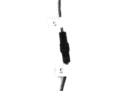
5.4 Before disconnecting the connector, label each wire
5. Raise the vehicle using a hydraulic lift.
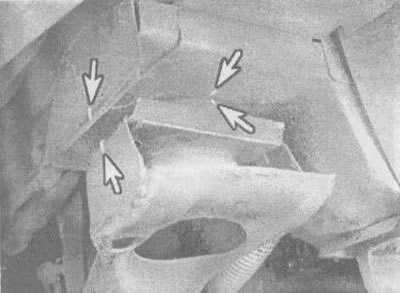
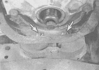
6. Working under the vehicle, complete the disconnection of all hoses, lines and wires (see illustrations). Don't forget to disconnect the three clamps securing the power steering line from the right side of the vehicle frame - they are located next to the crankshaft anti-vibration pulley. No further disassembly of the power steering system is required - all other components are attached to the subframe and can be removed with it.
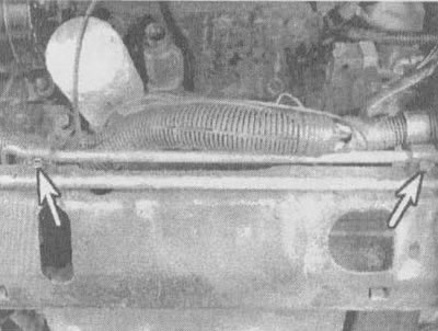
5.6a. With these two bolts (shown by arrows) the power steering radiator is attached to the subframe crossmember; they are also used to secure clamps for large wiring harnesses. Forgetting to disconnect these clamps will damage expensive wires when separating the car from the engine |
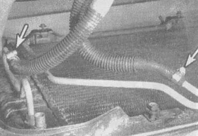
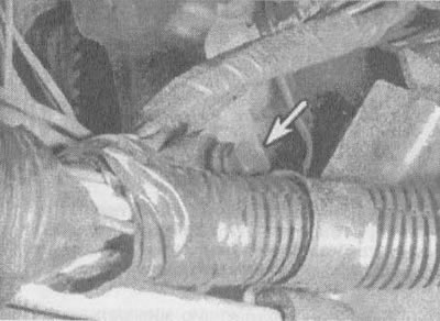
5.6b. Also, do not forget to disconnect the automatic transmission cooling radiator (shown by arrow) |
7. Drain the coolant from the cooling system (see chapter 1, section 29); tag and disconnect all coolant hoses from the engine.
8. Disconnect all fuel lines from the engine to the chassis (see chapter 4, section 4). Plug or seal all open fuel lines.
9. Disconnect the throttle cable and the economy mode cable (see chapter 4, section 9), as well as a "kick down" cable (see chapter 7, section 3).
10. Disconnect the air conditioner hoses from the compressor, move them to the side, disconnect the air conditioner from its support bracket and remove it from the engine compartment (see chapter 3, section 15).
11. Drain the oil from the engine and remove the filter (see chapter 1, section 12).
12. Disconnect the steering rods from the steering knuckles (see chapter 10, section 5).
13. Remove the starter (see chapter 5, section 17). Remove the flywheel cover (see illustrations).
5.13a. To remove the flywheel cover, unscrew these two bolts from below,... |
5.13b....one bolt at the back (to the thermal insulation partition)... |
5.13v....and one bolt in front
14. Scratch or paint a mark on the flywheel and torque converter (see illustration), then turn the crankshaft and unscrew the flywheel mounting bolts.
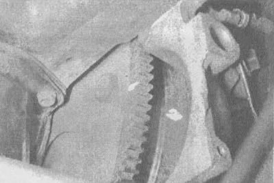
5.14. Make marks on the flywheel and torque converter to ensure that these parts are balanced against each other after assembly
15. Disconnect the engine shock absorber (see chapter 2, part 2.1, section 4).
16. Disconnect the exhaust system from the engine (see chapter 4, section 14).
17. Install 10x10 cm wooden blocks under both sides of the subframe to support the engine-gearbox-steering mechanism assembly.
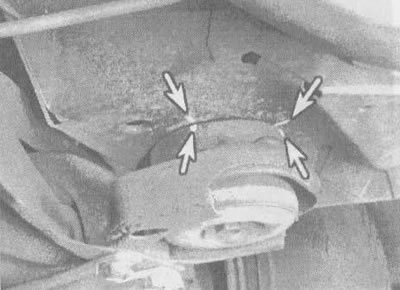
18. Draw marks on all four corners of the stretcher (see illustrations) and unscrew the four bolts (two front and two back) fastening the subframe to the frame. Check all four supports; if they are dry and cracked, replace them.
5.18a. Draw the marks (shown by arrows) between the corners of the subframe and the vehicle frame to ensure their correct installation during assembly (front right corner shown)... |
5.18b....and marks on the right rear corner of the subframe |
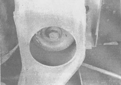
5.18v. Front bolt for fastening the subframe to the car |
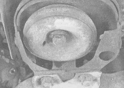
5.18g. Rear bolt for fastening the subframe to the car |
19. Raise the car enough to be sure that everything is disconnected (see illustration). Raise the vehicle to expose the engine-transmission-steering assembly.
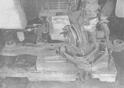
5.19. Before raising the vehicle high enough, make sure you have disconnected everything
20. Supporting the engine on a special lift, disconnect the flywheel mounts from the torque converter.
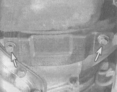
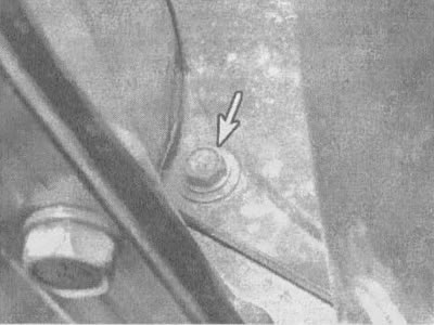
21. Unscrew the bolts and nuts on the engine support under the timing cover (see illustration).
5.21. To disconnect the engine from the subframe, unscrew these two nuts (shown by arrow) on the engine support under the timing cover
22. Make a final check that nothing connects the engine to the subframe.
23. Raise the engine slightly to separate it from the camshaft cover support. Carefully separate the engine from the gearbox. Make sure the torque converter is in place (to secure the torque converter, install a pair of clamps on the housing). Slowly lift the engine away from the subframe (see illustration). Check carefully that nothing is loose on the raised engine.
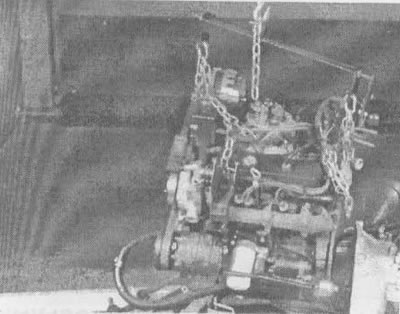
5.23. Raise the engine, separating it from the subframe using a lift
24. Remove the flywheel (see section 27) and install the engine on a special stand.
Installation
25. Before installing the engine, check the condition of the engine mounts and gearbox mounts (see chapter 7, section 8). If they are worn or damaged, replace the supports.
26. Carefully lower the engine onto the subframe. Make sure that the holes of the timing cover mounting bolts are aligned.
Caution: Do not use the transmission to engine mounting bolts to clamp the transmission to the engine. Be careful when aligning the torque converter to the flywheel using the procedures in Chapter 7, Section 9. Make sure that the marks you made on the flywheel and torque converter when removing the engine match up.
27. Lower the car onto the engine-gearbox-steering gear-subframe assembly. Install the subframe bolts, but do not tighten them yet. Using a pry bar or large screwdriver, align the subframe with the vehicle frame (see illustration), then tighten the subframe bolts to the torque specified in the specifications of this chapter.
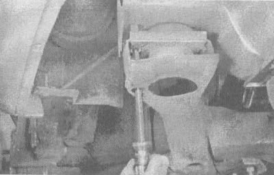
5.27. To align the subframe with the car frame, insert a pry bar or a large screwdriver into the holes in the subframe and frame and move the subframe until the marks you made on all four corners of the subframe align
28. Install the flywheel-to-torque converter mounting bolts and tighten them to the torque specified in the specifications in this chapter.
29. The remaining parts are installed in reverse order. Check several times to make sure everything is connected properly.
30. If necessary, add coolant, oil and hydraulic fluid to the power steering and transmission.
31. Start the engine and check for leaks and all components are working properly, then install the hood and take a test drive.