


Loosen the nut and remove the clamping bolt securing the lower end of the intermediate shaft 1 (see figure 5-2) to the steering gear screw shaft 11 (see figure 5-1).
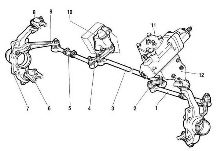
Figure 5-1. Steering gear assembly with drive:
1 - side pull;
2 - bipod;
3 - medium thrust;
4 - pendulum lever;
5 - adjusting coupling;
6 - lower suspension ball joint;
7 - right steering knuckle;
8 - Upper ball joint of suspension;
9 - right steering knuckle lever;
10 - pendulum arm bracket;
11 - steering mechanism;
12 - body side member.
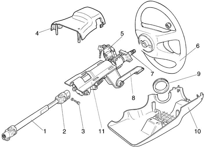
Figure 5-2. Steering column components:
1 - intermediate shaft with joint;
2 - cardan joint;
3 - tie bolt;
4 - upper casing;
5 - ignition switch;
6 - steering wheel;
7 - steering shaft;
8 - steering column tilt adjustment lever;
9 - sealing ring;
10 - lower casing;
11 - steering column bracket.
Remove the cotter pins and unscrew the nuts of the ball joints on the bipod 2, and use puller A.47035 to press the ball joints out of the bipod holes.
Remove oil from tank 9 (see figure 5-3) power steering.
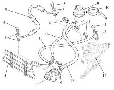
Figure 5-3. Power steering system:
1 - Power steering oil pump;
2 - heat exchanger;
3 - gasket 2108-3512115;
4 - bolt-nipple M16x1.5 2123-3408144;
5 - high pressure hose;
6 - screw clamp 2108-1300080-60;
7 - gasket 1/02824/60;
8 - bolt-nipple M14x1.5 2123-3408070;
9 - oil tank;
10 - Oil tank mounting bracket;
11 - screw clamp 2108-130008050;
12 - low pressure hose;
13 - low pressure drain hose;
14 - steering mechanism;
15 - supply hose.
Unscrew bolt 8 securing hose 5 to the steering gear and clamp 11 of hose 13 (see figure 5-3). Use technological plugs in the ends of the hoses to prevent loss of working fluid from the power steering system.
Loosen the nuts of the bolts securing the steering gear to the side member 12 (see figure 5-1) body and remove the steering gear.
Installation is performed in the reverse order of removal, and the following must be done:
- set the steering knuckle to the middle position;
- before tightening the nuts of the bolts 1 (figure 5-4), using a special device, orient the steering mechanism so that the angle a = 28°;
- check and adjust the front wheel alignment angles if necessary.
Filling the hydraulic system with oil and bleeding the hydraulic system.
- turn the wheels to the left as far as they will go and fill the power steering system with oil;
- bleed the system by turning the wheels from lock to lock 4...5 times, while monitoring the presence of oil in the tank;
- in extreme wheel positions, remove air from the steering gear by unscrewing the bleed nipple;
- check the oil level in the tank and run the engine briefly, check the oil in the tank. If necessary, add oil to the tank;
- start the engine and turn the wheels from lock to lock 2...3 times;
- turn off the engine and bleed the air from the steering gear again;
- check the oil level in the tank and, if necessary, top up the oil level to the norm. The oil level should be between the marks on the dipstick of the tank cap.
Warning. Before installing the hoses, check for cracks, tears, or sweating; replace with new ones if necessary. Replace the copper sealing gaskets of the high-pressure hose tips with new ones. To avoid pump failure, it is strictly prohibited to start the engine without oil in the hydraulic system or without bleeding the steering hydraulic system.
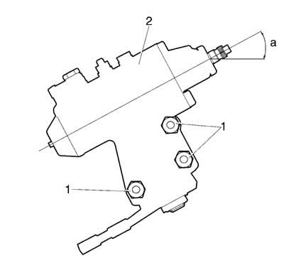
Figure 5-4. Installing the steering gear on the vehicle:
1 - steering gear mounting bolts;
2 - steering mechanism;
a - control angle.