


The main element of the front suspension is the telescopic shock absorber strut 5 (Fig. 7.1), which combines the functions of the telescopic element of the guide mechanism and the damping element of vertical oscillations of the wheel relative to the body. A coiled cylindrical spring, compression buffer, protective casing of the strut and the upper support are assembled on the shock absorber strut. The load is transmitted to the car body via the thrust bearing and the upper support. The lower part of the shock absorber strut 5 is connected to the steering knuckle 6 of the front suspension. The lever 8 of the suspension is attached to the subframe 1 using silent blocks 2 and 9, and via the ball joint 7 it is connected to the lower part of the steering knuckle 6 of the front suspension. The subframe, in turn, is attached to the side members of the body.
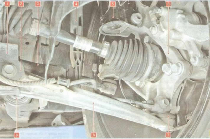
Fig. 7.1. Location of the front suspension elements on the vehicle: 1 - front suspension subframe; 2 - front hinge (silent block) suspension arm; 3 - stabilizer bar; 4 - anti-roll bar strut; 5 - shock absorber suspension strut; 6 - steering knuckle; 7 - suspension ball joint; 8 - front suspension arm; 9 - rear hinge (silent block) suspension arm
The anti-roll bar with rubber bushings installed on it is connected to the subframe 1 of the front suspension of the vehicle by two brackets, and to the shock absorber strut of the front suspension by the stabilizer struts 4.
The front wheel hubs are mounted on double-row radial thrust ball bearings.
[The original article can be found on the resource: «CHEVYMAN.RU»]