


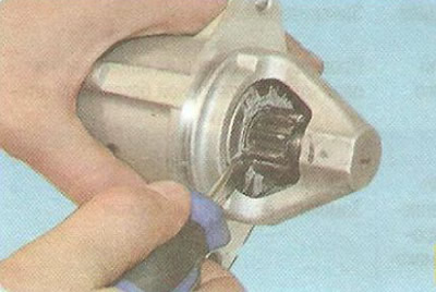
1. Using a screwdriver, check the ease of movement of the drive coupling along the shaft.
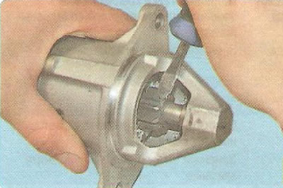
2. Turn the drive gear. It should easily turn relative to the clutch hub in the direction of rotation of the anchor and should not turn in the opposite direction.
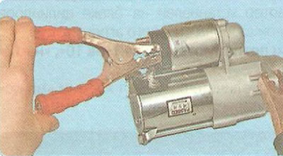
3. Connect the negative terminal of the battery removed from the vehicle to the starter housing using jumper wires. Connect one end of the second wire to the positive terminal of the battery and the other to the control wire terminal of the traction relay. If the traction relay is in good working order, a click will be heard and the drive clutch will extend. Otherwise, the traction relay must be replaced.
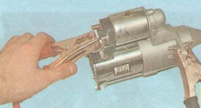
4. Disconnect the wire from the control terminal of the solenoid relay and connect it to the lower contact bolt of the solenoid relay. The starter rotor should begin to rotate at a frequency of more than 6000 min⁻¹. Otherwise, repair the starter.
You will need: 10 mm, 13 mm wrenches, TORX E5 and E7 wrenches, flat- and Phillips-head screwdrivers, narrow-jaw pliers, a hammer, a tester, and a caliper.
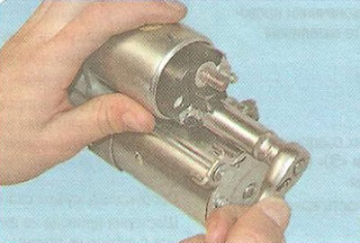
1. Unscrew the nut securing the busbar to the contact bolt of the traction relay...
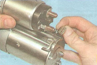
2. ...and disconnect the tire from the bolt.
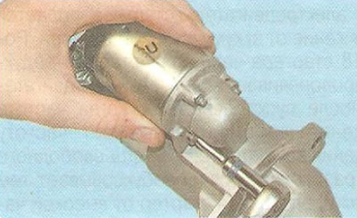
3. Remove the three bolts securing the traction relay to the front cover...
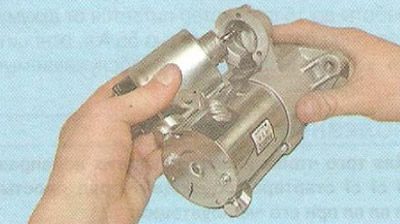
4. ...and remove the traction relay.
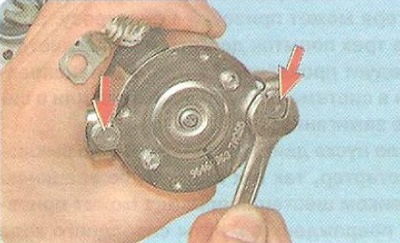
5. Unscrew the two tie bolts...
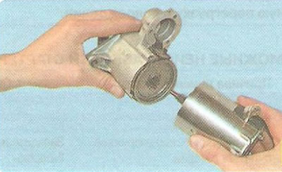
6. ...and separate the stator and the back cover.
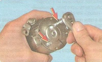
7. Remove the two cover mounting bolts...
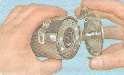
8. ...and remove the lid.
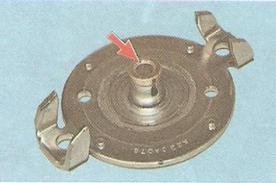
9. Inspect the rear cover. If the bushing in the cover is worn out or has burrs, cavities or other defects, it is necessary to replace the bushing or the cover assembly with the bushing.
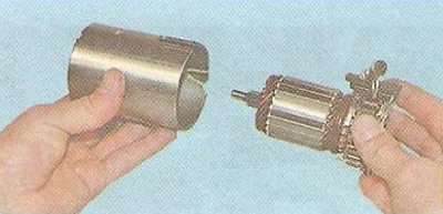
10. Remove the rotor assembly with the brush unit from the stator.
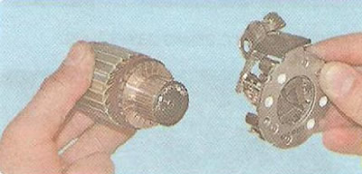
11. Remove the brush assembly from the rotor.
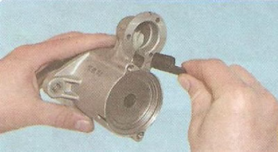
12. Remove the starter drive lever support from the front cover.
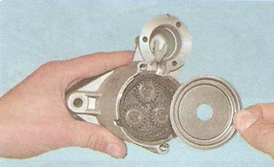
13. Remove the planetary gear oil deflector cover...
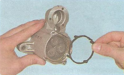
14. ...and a sealing ring.
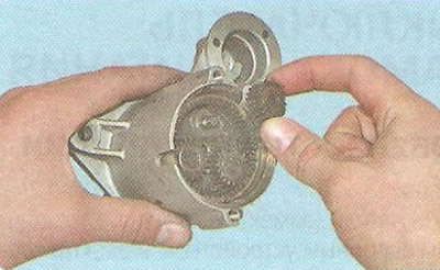
15. Remove three satellites from the carrier axles.
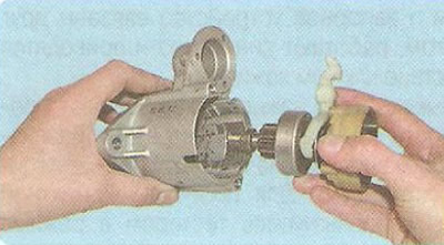
16. Remove the drive shaft from the cover...
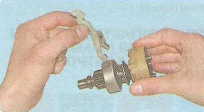
17. ...and remove the drive lever.
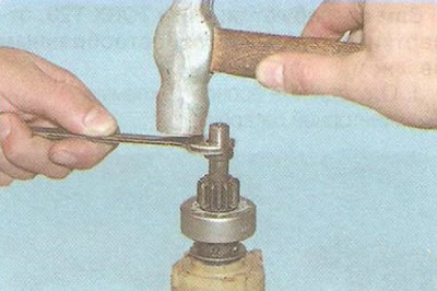
18. Slide the stop ring along the drive shaft as shown in the photo.
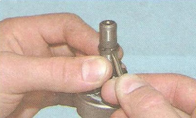
19. Use a screwdriver to pry up and remove the retaining ring.
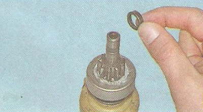
20. Remove the restrictor ring...
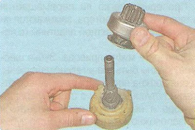
21. ...and the drive clutch.
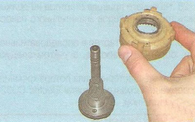
22. Remove the planetary gear ring gear.
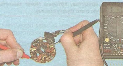
23. Inspect the brush assembly. Check the height of the brushes in the brush holder. If their height is 7 mm or less, replace the brush assembly with a new one. Use an ohmmeter to check the insulated holders for short circuit with the housing. The resistance should tend to infinity.
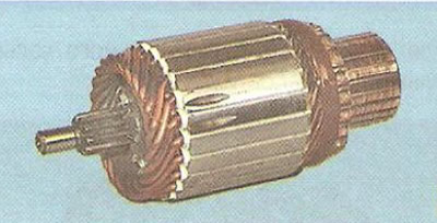
24. Inspect the rotor. There should be no damage to the rotor shaft pinion or journals (nicks, burrs). The rotor collector should not have any signs of burning. Remove minor burning with a rag soaked in gasoline and fine-grained sandpaper.
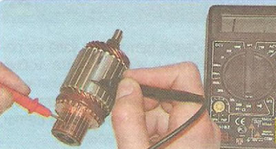
25. Check the rotor winding for short circuit using an ohmmeter. The resistance should tend to infinity.
26. Check whether the starter traction relay anchor moves easily and whether the contact bolts of the contact plate close (using an ohmmeter).
27. Check the drive coupling. The gear teeth should not be significantly worn. The gear should easily rotate relative to the coupling hub in the direction of rotor rotation and should not rotate in the opposite direction. If the gear teeth are worn or damaged, or the gear rotates in both directions, replace the coupling.
28. There should be no cracks or signs of significant wear on the starter drive lever.
29. Assemble the starter in the reverse order of disassembly, taking into account the following:
- lubricate the rotor shaft gear with General Electric CG321 silicon grease or equivalent;
Warning: During operation, the drive coupling does not need to be lubricated. However, it must be cleaned of dirt. Do not use any means to clean the drive that may wash out the lubricant contained in the coupling.
- lubricate the bearings (bushings) in which the starter rotor rotates with engine oil;
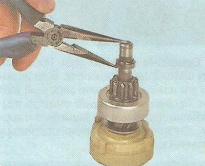
- use pliers to install the stop ring;
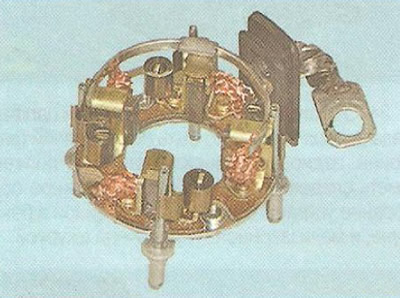
- before installing the brush assembly on the rotor, spread the brushes and secure them in any way possible (for example, with rivets or small nails). After installing the brush assembly on the rotor, release the brushes by removing the installed locks;
- before installing the traction relay, apply a thin layer of silicone sealant to the surface of the relay that contacts the starter cover on the drive side.
The material was created based on information from the website: «chevyman»