


Manual transmission (fig. 6.4, 6.5) is made according to a two-shaft scheme with five synchronized forward gears and one unsynchronized reverse gear. The gearbox and the main gear with the differential have a common housing, and in addition, the gearbox has an additional intermediate housing and cover. The primary shaft is pressed into the gear block and connected to it by splines.
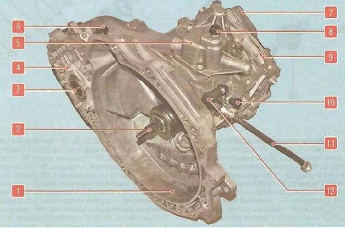
Fig. 6.4. Manual gearbox: 1 - gearbox housing; 2 - primary shaft; 3 - axle shaft seal; 4 - main gear housing; 5 - gear shift mechanism; b - speed sensor; 7 - rear cover of the gearbox; 8 - breather; 9 - intermediate crankcase; 10 - Reverse light switch; I - clutch release hydraulic hose; 12 - Clutch release hydraulic hose adapter
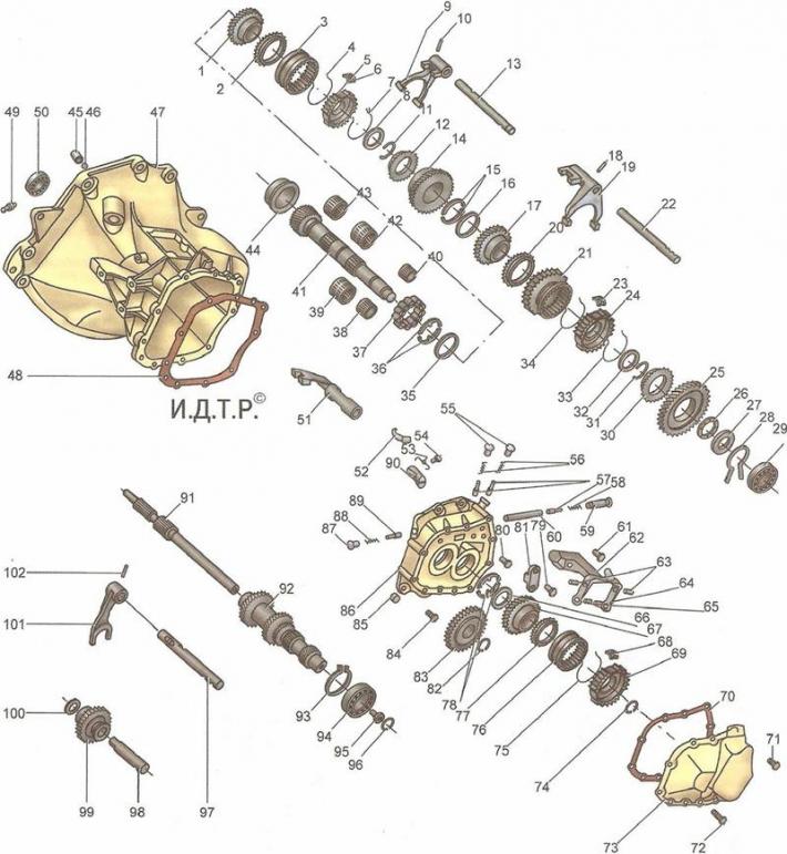
Fig. 6.5. Details of a manual gearbox: 1 - 4th gear pinion; 2, 12, 20, 30, 77 - synchronizer locking rings; 3 - clutch for engaging synchronizer of III and IV gears; 4, 7, 33, 34,75 - synchronizer spring rings; 5 - synchronizer hub for 3rd and 4th gears; b, 23, 68 - synchronizer crackers; 8, 32 - thrust washers; 9 - fork for shifting III and IV gears; 10, 18, 102 - pins; 11, 31, 74, 82, 93, 96 - retaining rings; 13 - fork rod for shifting III and IV gears; 14 - third gear pinion; 15, 36, 78 - thrust half rings; 16, 35, 66 - locking rings; 17 - 2nd gear pinion; 19 - fork for shifting 1st and 2nd gears; 21 - I and II gear synchronizer engagement clutch; 22 - 1st and 2nd gear shift fork rod; 24 - synchronizer hub for 1st and 2nd gears; 25 - 1st gear pinion; 26 - thrust needle bearing of 1st gear; 27 - support washer; 28 - spring ring; 29 - secondary shaft bearing; 37 - secondary shaft roller bearing; 38 - needle bearing of 1st gear; 39 - needle bearing of the 2nd gear pinion; 40 - needle bearing of the V gear; 41 - secondary shaft; 42 - needle bearing of the third gear pinion; 43 - needle bearing of the 4th gear pinion; 44 - outer ring of secondary shaft roller bearing; 45 - cork; 46 - magnet; 47 - gearbox housing; 48 - Clutch housing gasket; 49 - Reversing light switch; 50 - primary shaft roller bearing; 51 - leash with V gear rod; 52 - dog; 53 - pawl spring; 54, 61, 71, 72, 79, 81, 84 - bolts; 55, 59, 87 - retainer plugs; 56, 58, 88 - springs; 57, 89 - clamps; 60 - locking mechanism pin; 62 - V-gear shift fork bracket; 63 - V gear fork axis; 64 - V gear engagement fork; 65 - Fork crackers; 67 - driven gear of the 5th gear; 69 - 5th gear synchronizer hub; 70 - cover gasket; 73 - rear cover of gearbox; 76 - 5th gear synchronizer engagement clutch; 80 - pawl bracket; 83 - V-gear drive gear; 85 - magnet; 86 - intermediate crankcase; 90 - pawl bracket; 91 - primary shaft; 92 - gear block; 94 - Gear block ball bearing; 95 - screw; 97 - reverse intermediate gear engagement fork rod; 98 - reverse intermediate gear axle; 99 - reverse intermediate gear; 100 - washer; 101 - Reverse intermediate gear engagement fork
The secondary shaft of the gearbox contains the leading cylindrical gear of the main transmission, driven gears and gear synchronizers. The pairs of forward gears of the gearbox are in constant engagement. The gears of the fourth gear in the neutral position rotate freely on the secondary shaft.
Forward gears are engaged by axial movement of the corresponding synchronizer clutches mounted on the secondary shaft. Reverse gear is engaged by moving the intermediate reverse gear along its axis.
The gear shift mechanism is located in a cover mounted on top of the gearbox housing.
Manual transmission control drive cable type. Lever 1 (see fig. 6.7) the manual gearbox shift lever together with bracket 2 is installed in the passenger compartment at the base of the body in the floor tunnel. The lever is connected to the levers 5 of the control unit on the gearbox by cables 3 and 4.
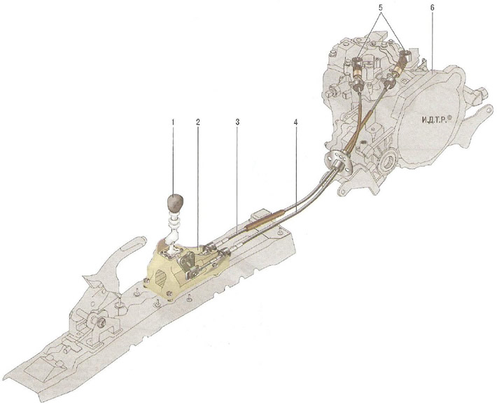
Fig. 6.7. Manual transmission control drive: 1 - gear shift lever; 2 - gear shift lever bracket; 3 - gear shift cable; 4 - gear selection cable; 5 - gear shift levers; 6 - manual gearbox
Main gear (Fig. 6.6) is made in the form of a pair of cylindrical gears, selected for noise. Torque is transmitted from the driven gear of the main transmission to the differential and then to the front wheel drives.
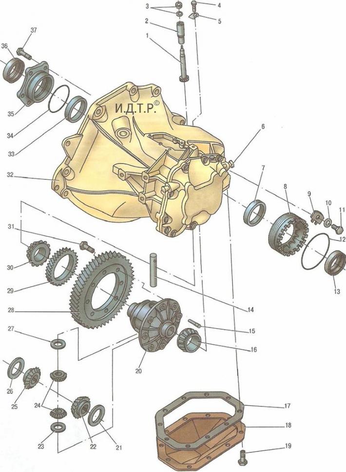
Fig. 6.6. Main gear and differential: 1 - speedometer drive gear shaft; 2 - speedometer drive gearbox housing; 3, 12, 34 - sealing rings; 4, 11, 19, 31, 37 - bolts; 5 - locking plate; 6 - rear cover of the gearbox; 7, 33 - outer rings of differential bearings; 8 - bearing adjusting nut; 9 - retainer plate; 10 - washer; 13, 36 - oil seals; 14 - differential satellite axle; 15 - satellite axle lock; 16, 30 - tapered roller bearings of the differential; 17 - gasket; 18 - gearbox lower cover; 20 - differential housing; 21, 26 - thrust washers; 22, 25 - axle gears; 23, 27 - satellite thrust washers; 24 - satellites; 28 - driven gear of the main transmission; 29 - speedometer drive pinion; 32 - gearbox housing; 35 - right differential bearing cover
Differential bevel, two-satellite. The tightness of the connection of the internal joints of the front wheel drives with the differential gears is ensured by seals 3 (see fig. 6.4), 13 (see fig. 6.6) and 36.
Automatic transmission (Fig. 6.8) provides the choice of the optimal gear shift mode for virtually any driving style and road conditions.
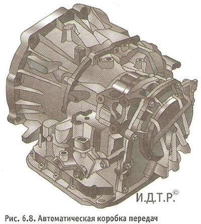
It is arranged according to the traditional planetary scheme with friction braking and is connected to the engine crankshaft via a torque converter. A special feature of the Chevrolet Cruze gearbox is the ability to switch from a fully automatic control mode to a semi-automatic mode, in which the driver, depending on driving conditions, can forcibly block automatic switching to higher gears. The automatic gearbox control algorithm is described in detail in "Gearbox control".
The automatic transmission control drive is cable-operated. The gearbox control selector lever 7 (Fig. 6.9) is installed in the same place on the floor tunnel as the manual transmission control lever. The selector lever is connected to the control unit lever 11 on the gearbox by cable 4.
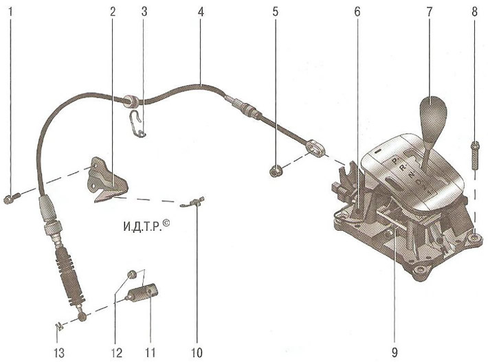
Fig. 6.9. Automatic transmission control drive: 1 - bolt for fastening the control cable bracket to the gearbox; 2 - bracket for fastening the control cable to the gearbox; 3 - control cable holder on the body; 4 - gearbox control cable; 5 - nut securing the cable end to the gearbox selector lever; 6 - gearbox selector lever bracket; 7 - Automatic transmission selector lever; 8 - bolt for fastening the bracket to the body base; 9 - mechanism bracket; 10 - cable sheath retainer; 11 - gearbox control lever; 12 - nut securing the gearbox control lever to the gearbox control unit shaft; 13 - Cable tip retainer
Differential the design of the automatic transmission differential is completely similar to that of the manual transmission differential.
To repair an automatic transmission, a large set of special tools and appropriate training of the performer are required, therefore, if it is necessary to repair the transmission, contact a specialized service.
[The article was reprinted from the website: CHEVYMAN.RU]