


Removal and installation. If only the oil pump needs to be repaired, remove the engine from the vehicle (see subsection "Removal and installation the engine"), install on a rotary stand, drain the oil from the crankcase, turn the engine over and remove the crankcase. Then unscrew the oil pump mounting bolts and remove it together with the intake pipe.
Perform operations for installing the oil pump on the engine in the reverse order of removal.
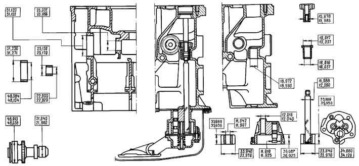
Figure 2-68. Main dimensions of the oil pump parts and its drive.
Disassembly and assembly. Secure the oil pump in a vice, being careful not to damage the housing, and then:
- unscrew the mounting bolts and remove the intake pipe together with the oil pressure reducing valve;
- remove cover 3 (figure 2-69) pump housing and remove the pump shaft with the drive gear and the driven gear from the housing.
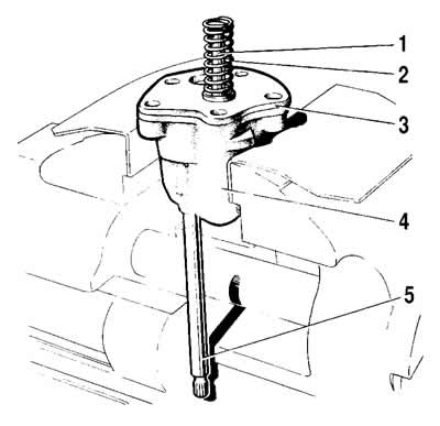
Figure 2-69. Disassembling the oil pump:
1 - pressure reducing valve;
2 - valve spring;
3 - lid;
4 - body;
5 - roller.
To assemble, carefully secure the pump body in a vice and perform the following operations:
- install the drive gear with the shaft into the pump body, put the driven gear on the axle in the body;
- install the pump cover, pressure reducing valve with spring and attach the inlet pipe to the pump body.
Note: After assembling the pump, when turning the drive shaft by hand, the gears should rotate smoothly and without jamming.
Checking the pump parts. After disassembling, wash all the pump parts with kerosene or gasoline, blow with a stream of compressed air, and then inspect the pump body and cover; if there are cracks, replace the parts with new ones.
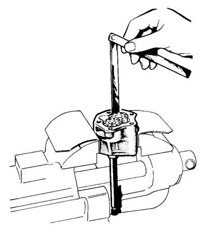
Figure 2-70. Checking the radial clearance in the oil pump.
Use a set of feeler gauges to check the gaps between the gear teeth, as well as between the outer diameters of the gears and the walls of the pump housing (figure 2-70), which should be 0.15 mm respectively (maximum permissible 0.25 mm) and 0.11-0.18 mm (maximum permissible 0.25 mm). If the gaps exceed the maximum permissible values, replace the gears and, if necessary, the pump housing.
With a feeler gauge and a ruler (figure 2-71) check the gap between the ends of the gears and the plane of the housing, which should be equal to 0.066-0.161 mm (maximum permissible 0.20 mm). If the clearance is greater than 0.20 mm, replace the gears or the pump housing, depending on which is worn.
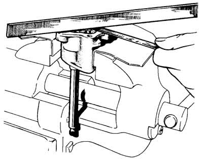
Figure 2-71. Checking the axial clearance in the oil pump.
After measuring the parts, determine the gap between the driven gear and its axis, which should be 0.017-0.057 mm (maximum permissible 0.10 mm), and also between the pump shaft and the hole in the housing. This gap should be 0.016-0.055 mm (maximum permissible 0.10 mm). If the gaps exceed the maximum allowable limits, replace the worn parts.
Checking the pressure relief valve. When repairing the oil pump, check the pressure relief valve. Pay attention to the surfaces of the valve and the holes in the intake pipe, as possible contamination or deposits on the mating surfaces can cause the valve to stick.
The mating surfaces of the valve and pump cover must be free of nicks and burrs that could lead to a decrease in oil pressure in the system.
Check the elasticity of the pressure reducing valve spring, compare the obtained data with those shown in Figure 2-72.
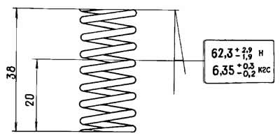
Figure 2-72. Basic data for checking the pressure reducing valve spring.