


Contents: Examination ↧ Repair ↧
1. The rear window defroster consists of multiple horizontal heating elements fused to the glass surface. Power supply is provided through a large fuse located in the outdoor unit (which is located in the engine compartment). The heating is controlled via a switch located on the instrument panel.
2. Elements with minor breaks can be restored without removing the rear window.
Examination
3. Set the ignition switch and heater switch to the ON position.
4. Connect the positive electrode of the voltmeter to the positive terminal of the heating element and the negative electrode to the terminal of the heater ground circuit. If the device does not detect the presence of voltage generated by the battery, inspect the fuse, heating switch and related wiring. If voltage is present but the entire heating element or section is not working, perform the following check.
5. When measuring voltage during the next two tests, wrap the negative electrode of the voltmeter with aluminum foil and take measurements by pressing the foil to the heating element with your finger (see illustration). Connect the negative electrode to the ground terminal of the heating element.
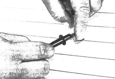
21.5. To measure the voltage in the rear window defroster sections, wrap the negative electrode of the voltmeter with aluminum foil and press the foil to the element with your fingers
6. Measure the voltage by connecting the foil-wrapped electrode to the center of each section of the element one by one (see illustration). If the voltage is 5-6 V, this indicates that the section is not broken. A zero voltage measurement result indicates a break between the center of the section and the ground contact terminal. A voltage of 10-12 V indicates a break in the section between the center and the ground loop. Explore each section of the heater.
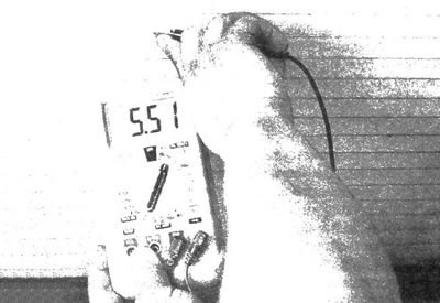
21.6. When identifying a section of the heating element that has a break, measure the voltage by connecting a foil-wrapped electrode to the center of each section. If the voltage is 6 V, this indicates that the element is in good condition
7. If no break is found in the element, connect the negative electrode of the voltmeter to the ground point on the vehicle body. If the ground loop is not open or shorted, the voltmeter readings should not change.
8. To locate the open circuit in the heating element, connect the negative electrode of the voltmeter to the ground contact terminal of the rear window heater. Connect the positive electrode of the voltmeter, wrapped in foil, to the positive contact terminal of the heating element, then move the electrode along the element towards the negative contact terminal. The point at which the voltmeter reading deviates by several volts from the zero mark is the breaking point of the heating element (see illustration).
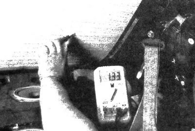
21.8. To locate the break in the heating element, connect the negative electrode of the voltmeter to the ground contact terminal of the rear window heater; connect the positive electrode of the voltmeter, wrapped in foil, to the positive contact terminal of the heating element and move the electrode along the element towards the negative contact terminal; the point at which the voltmeter reading deviates by several volts from the zero mark corresponds to a break in the heating element
Repair
9. Repair the heating element break using a special repair kit (for example, DuPont paste No. 4817 or similar). The kit also includes a plastic conductive epoxy resin.
10. Turn off the heater and wait for it to cool for a few minutes, then fix the break.
11. Sand the area adjacent to the break, then degrease it with alcohol
12. Apply two strips of adhesive tape to the glass to insulate the area of the heating element to be repaired.
13. Prepare the restoration compound from the repair kit, following the accompanying instructions.
14. Apply the composition to the area to be repaired between the strips of tape, overlapping the torn element by 20 mm on each side (see illustration).
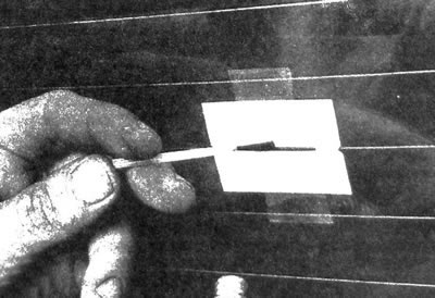
21.14. Before restoring the element using the repair kit, cover the damaged area with tape, then apply the restorative compound
15. No sooner than after 24 hours, remove the adhesive tape strips and check the functionality of the restored element.
The original article can be found on the resource: «CHEVYMAN»