
Contents: Heating switches ↧ Blowing nozzles ↧
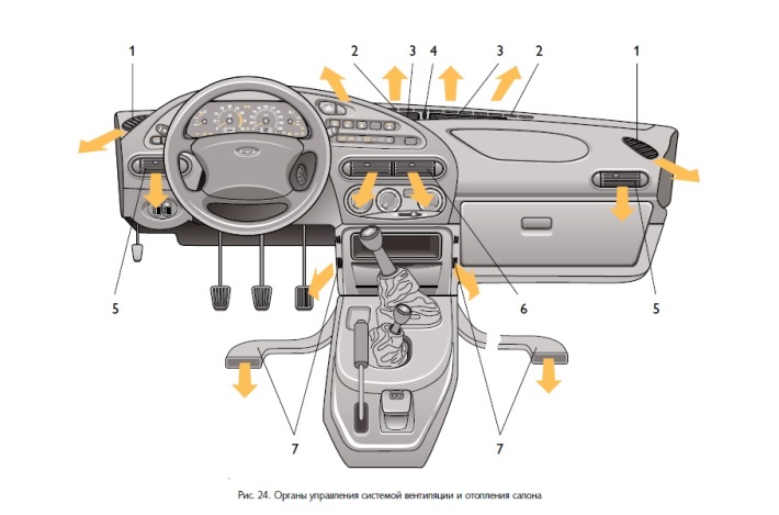
1. Nozzles for blowing air from windows and front doors.
2. Upper slots of the instrument panel.
3. Upper blower nozzles.
4. Regulator of additional air supply through the upper nozzles.
5. Side blower nozzles.
6. Central blowing nozzles.
7. Lower blower nozzles.
Ventilation and heating of the passenger compartment are regulated depending on the outside air temperature by mixing cold and heated air and are maintained at a virtually constant level at any vehicle speed. Figure 24 shows the controls for the ventilation and heating system of the vehicle's passenger compartment.
Heating switches
Left rotary switch:
Temperature, Figure 25.
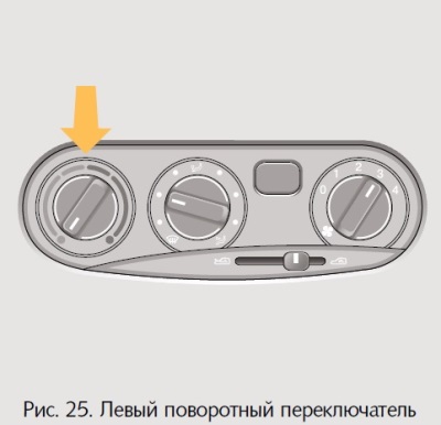
- Turn right = warmer
- Turn left = cooler
Middle rotary switch:
Air distribution, Figure 26.
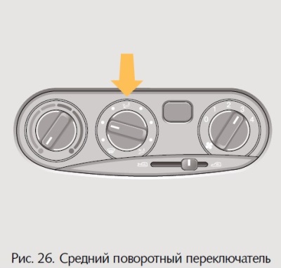
- the air flow is supplied through nozzles to the upper part of the cabin, preventing icing of the windows;
- the air flow is supplied through the lower nozzles to the driver and passenger footwell area;
- the air flow is supplied through the side and central nozzles.
Right rotary switch:
Blowing (fan), figure 27.
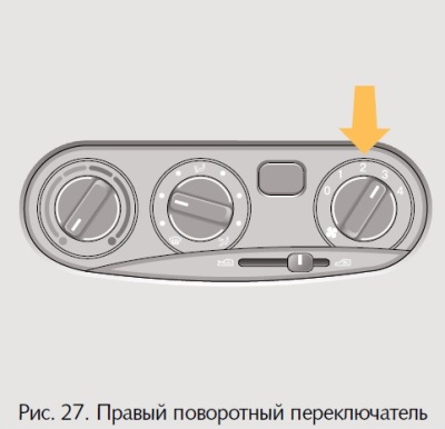
Four speeds:
- 0 – off
- 4 – maximum air flow.
The blower fan allows you to increase the volume of incoming air, which provides additional comfort when driving and accelerated removal of ice and heating of the cabin. Therefore, it is necessary to turn on the blower while driving.
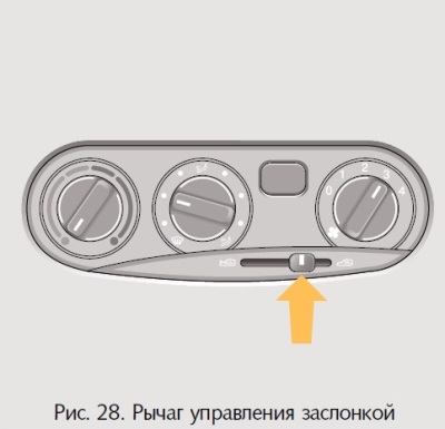
Figure 28 shows the damper control lever:
- in the extreme left position, outside air enters the cabin;
- in the middle position of the lever the outside air and the air are mixed,
- circulating inside the cabin;
- in the extreme right position, the recirculation mode is activated.
When the recirculation mode is turned on, the supply of outside air is blocked. This mode can be useful, for example, when driving through a tunnel or when driving in a traffic jam to prevent exhaust-laden air from entering the passenger compartment. Long-term air circulation inside the car can cause the windows to fog up.
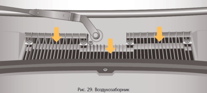
The heater air intake, Figure 29, is located under the soundproofing trim in the engine compartment under the windshield wiper arm shafts. The air intake openings must be free for air to flow in, and if necessary, remove leaves, dirt or snow.
The air filter is installed in the air intake box of the heater, which cleans the air entering the cabin from dust, soot, plant pollen, etc.
Blowing nozzles
Central blower nozzles, figure 30.
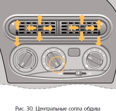
The air supply is regulated by levers 1 of the guide vanes of the central nozzles by changing the position of the flaps up or down, and the air supply intensity regulator 2 opens or completely closes the central blower nozzles. Depending on the position of the temperature switch, comfortable blowing of the upper space of the passenger compartment with unheated or warm air is ensured.
To increase the air flow, turn on the blower fan and set the middle rotary switch to position.
Side air nozzles, figure 31.
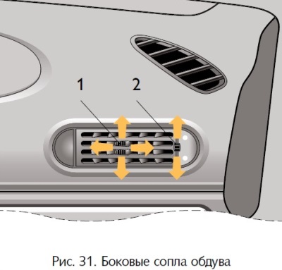
Normal or warm air enters the passenger compartment through the nozzles. The air supply is regulated by levers 1 of the guide blades of the side nozzles by changing the position of the flaps up or down, and the air supply intensity regulator 2 opens or completely closes the side blower nozzles.
The air flow direction can be adjusted to create a warm air cushion in the door area in cold weather.
To increase the air flow, turn on the blower fan and set the middle rotary switch to position.
Nozzles for blowing air from windows and front doors, Fig. 32.
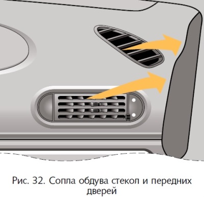
Set the damper control lever to the extreme left position and the middle rotary switch to the position: cold or warm air will be directed towards the windshield and side windows (mainly in areas where exterior mirrors are installed).
Upper blower nozzles, figure 33.
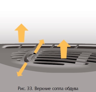
Set the throttle control lever to the extreme left position and the center rotary switch to the position:
- cold or warm air will be directed towards the windshield;
- middle rotary switch in position;
- when the damper is open, the additional air supply regulator provides additional air supply.
Lower blower nozzles, figure 34.
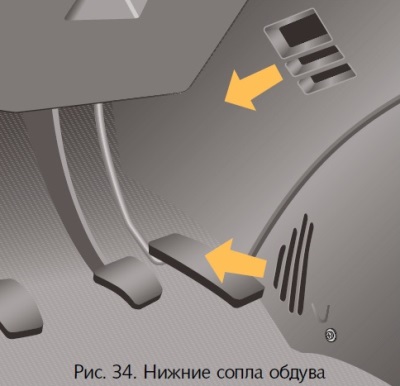
Unheated or warm air is supplied to the lower part of the cabin (in the driver and passenger footwells). To increase the air flow, switch the blower fan to a higher level and set the air distributor middle rotary switch to position.
Cabin ventilation, figure 35.
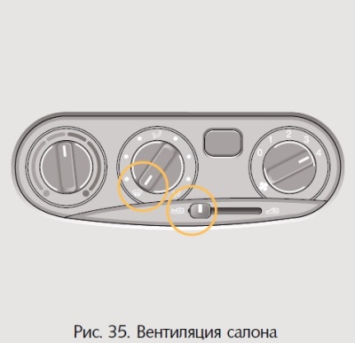
In the extreme left position of the damper control lever, outside air enters the vehicle interior:
- through the upper air vents and the front door glass air vents if the middle rotary switch is set to position;
- through the side and central nozzles,
- if the middle rotary switch is moved to position.
The air supply intensity regulators through the side and central nozzles regulate the air supply by changing the position of the flaps up to their complete closure. In this position, with the flap open, the additional air supply regulator through the upper nozzles provides additional air supply.
- through the lower nozzles into the driver and passenger footwell area if the center rotary switch is in position. When the levers of the guide vanes of the side and center nozzles are turned, the direction of the air flow changes.
To increase the air supply to the vehicle interior, set the right rotary switch to one of the four heater fan modes.
The original text can be found on the website: «CHEVYMAN.RU»