
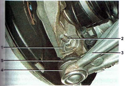
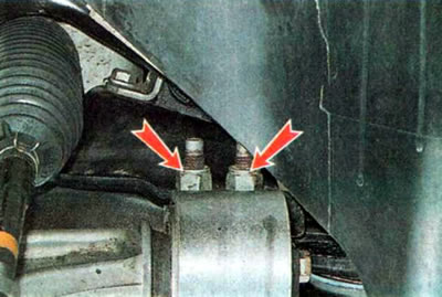
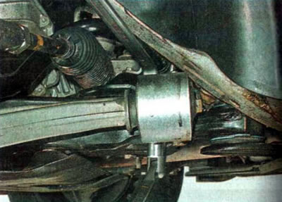
1 — steering knuckle eye; 2 — bolt of the clamping clamp for fastening the ball joint pin to the steering knuckle; 3 — front suspension arm; 4 — ball joint housing; 5 — ball joint pin cover
During operation, the ball joint experiences heavy loads, the friction surface of the pin and the bearing liners wear out, which leads to an increase in the gap between the bearing body and the pin. As a result, the finger begins to move along its axis, and a knock appears. A rupture of the protective cover will lead to intensive wear of the ball joint, as a result of which dirt and moisture will inevitably get inside. Failure to replace the support in a timely manner may result in the support being destroyed and an emergency situation arising. The ball joint is assembled with the lever. The need to replace the lever is determined during the inspection of the condition of the front suspension.
Removal and installation the lever
To perform the work you will need a car stand, a jack, wheel chocks, and a ball joint puller.
1. Prepare the car for maintenance and repair, install chocks under the rear wheel and lift the front part of the car.
2. Remove the wheel.
3. Using a metal brush, clean the nut and threads of the tie bolt from dirt and rust...
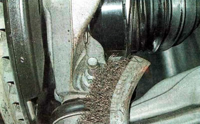
...and treat them with penetrating lubricant.
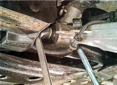
4. Similarly, we process the front fastenings...
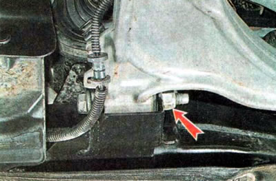
... and the rear support of the lever.
5. Using a slotted screwdriver, disconnect the wheel speed sensor wire from the lever bracket.
6. Using a 15 mm wrench, unscrew the nut of the ball joint pin mounting bolt, holding the bolt from turning with a wrench of the same size.
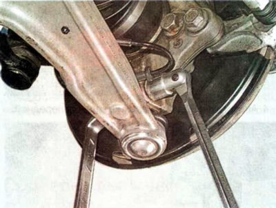
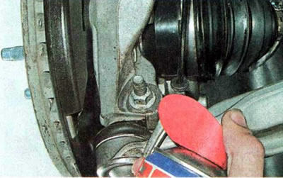
7. Using a mounting blade, loosen the clamp and disconnect the ball joint pin from the steering knuckle.
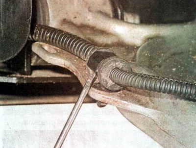
8. Using an 18 mm wrench, unscrew the nut of the front suspension arm support bolt, holding the bolt from turning with a wrench of the same size, and remove the bolt.
9. Similarly, unscrew the nuts of the bolts securing the rear support of the suspension arm.
10. Remove the lever from the car.
11. Install the lever in the reverse order without fully tightening the nuts of the front and rear support bolts.
12. Insert the ball joint pin into the steering knuckle clamp and tighten the bolt nut to the specified torque.
13. Install the wheel and lower the car onto the supporting surface.
14. Tighten the lever mounting bolts to the specified torques.
Recommendation. After performing work related to disconnecting the lever, check and adjust the wheel alignment angles.