


Contents: Replacement of elements ↧ Adsorber ↧ Blow-off valve ↧ Ventilation valve ↧ Fuel tank pressure sensor ↧
1. The EVAP (Evaporative Emissions Protection) system is designed to prevent the emission of unburned hydrocarbons into the atmosphere. The vapors enter the adsorber and are then fed into the intake manifold of the running engine and, mixing with the supplied fuel-air mixture, burn in the cylinders of the power unit. The system consists of the following main elements: adsorber (a carbon filter that adsorbs and retains fuel vapors), purge valve of the adsorber, ventilation valve, fuel pressure sensor in the tank, fuel tank, as well as purge and ventilation lines.
2. After passing the control valve, vapors from the fuel tank enter the adsorber through the evaporation hose, where they are adsorbed into the activated carbon filler and retained. When the operating parameters for which the system is programmed are reached (the engine is running, its temperature has reached a certain limit, etc.) the PCM sends a signal to open the purge valve and the ventilation valve. Fuel vapors are drawn from the adsorber through the purge hose into the intake manifold (due to the vacuum created), where they are mixed with the fuel-air mixture before entering the combustion chambers.
3. The flow rate of fuel vapor directed from the canister to the intake manifold is controlled in the PCM by changing the cycle of the EVAP purge valve. When the engine is running cold or when the starting time of a warm engine is delayed, the PCM does not send a control signal to the valve solenoid. After the power unit has warmed up to operating temperature, the PCM control unit sends a signal to the purge valve solenoid, and vapors are supplied to the intake manifold at a flow rate depending on the engine operating mode. Purge valve duty cycle (switching on and then switching off) occurs 5 to 10 times per second. The gas flow is controlled by changing the valve pulse width (duration of signal supply to the solenoid).
4. When starting a cold engine, the EVAP system self-diagnoses. When certain operating parameters are reached, the PCM sends a signal to open the purge valve, while the ventilation valve remains closed. At the same time, the EVAP system is supplied with a vacuum created in the engine. When a certain degree of vacuum is reached, the purge valve closes, thus sealing the system. The PCM analyzes the signal from the fuel tank pressure sensor and, if a system leak is detected, a corresponding diagnostic trouble code is recorded in the electronic memory of the microprocessor.
5. The operating principle of the fuel tank pressure sensor is similar to the operating principle of the manifold absolute pressure (MAP) sensor. In the PCM, the 5-volt sensor circuit is closed, as well as its ground loop. The sensor sends a signal to the PCM, which changes depending on the vapor pressure in the fuel tank. When equalizing the pressure in the tank with atmospheric pressure (as if the gas cap was removed) the output signal of the sensor has a potential of approximately 1.5 V. With a vacuum in the tank of 356 mm Hg, the output potential of the sensor is 4.5 V.
Note: The fuel vapor recovery system, like all emission control systems, is guaranteed to operate without interruption (at the time of this manual's creation, the warranty was for 5 years or 80,000 km).
Replacement of elements
6. All EVAP system hoses have quick-disconnect couplings. Before disconnecting, it is necessary to clean the coupling and the area around it. Rotate the coupling elements relative to each other to release the seal. When disconnecting a larger diameter hose coupling, it is necessary to squeeze the tabs of the retainer and pull it off the tube. To disconnect a hose of a smaller diameter, it is necessary to press in the locking tab and pull the coupling off the tube.
Adsorber
7. The EVAP canister is attached to a bracket next to the fuel tank.
8. Raise the vehicle and support it on vertical stands.
9. If necessary, remove the fuel tank protective panel.
10. Disconnect the hoses from the adsorber (see illustration).
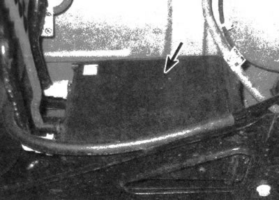
15.10. The EVAP system canister is located near the gas tank
11. Unscrew the bracket bolt and remove the adsorber.
12. Installation is carried out in the reverse order of removal.
Blow-off valve
13. The purge valve is located on the left side of the engine. It is mounted on a bracket that is located above the starter (see illustrations).
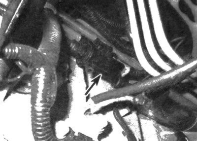
15.13 The EVAP purge valve/control solenoid is located on the left side of the engine block
14. Disconnect the electrical connector.
15. Press in the locking tab and disconnect the hose from the purge valve.
16. Unscrew the mounting bolt/nuts.
17. Remove the purge valve.
18. Installation is carried out in the reverse order of removal.
Ventilation valve
19. The ventilation valve is mounted on a bracket near the gas tank (see illustration).
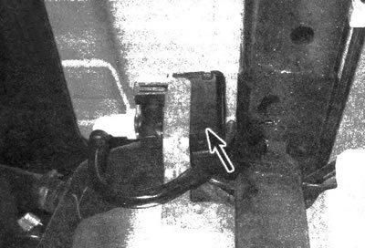
15.19. EVAP Vent Valve/Control Solenoid Location
20. Raise the vehicle and support it on vertical stands.
21. Disconnect the electrical connector.
22. Disconnect the hose from the ventilation valve (see item 9).
23. Disconnect the clips and remove the ventilation valve from the bracket.
24. Installation is carried out in the reverse order of removal.
Fuel tank pressure sensor
25. The fuel tank pressure sensor is located in the fuel pump module (see illustration).
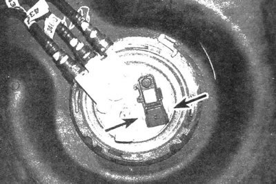
15.25. The location of the sensor in the fuel tank, to remove it, it must be compressed from the sides
26. Remove the fuel tank (see chapter 4).
27. Disconnect the electrical connector from the fuel tank pressure sensor.
28. Disconnect the retainer and remove the sensor from the top of the fuel pump module.
29. Installation is carried out in the reverse order of removal.