


Contents: Diagnostic Trouble Code Table ↧ Diagnostic Trouble Code (DTC) B0012 ↧ Front Airbag Deployment Circuit:… ↧ Code B0012 - "Resistance Too High"… ↧ Code B0012 - "Resistance too low"… ↧ Code B0012 - "Short to Ground" Front… ↧ Code B0012 - "Short to Battery"… ↧ Diagnostic Trouble Code (DTC) B0014 ↧ Side airbag deployment chain: left… ↧ Code B0014 - "Resistance Too High"… ↧ Code B0014 - "Resistance too low"… ↧ Code B0014 - "Short to Ground" Side… ↧ Code B0014 - "Short to Battery" Side… ↧ Diagnostic Trouble Code (DTC) B0015 ↧ Seat belt tensioner circuit: left… ↧ Code B0015 - Seat Belt Pretensioner… ↧ Code B0015 - Seat Belt Pretensioner… ↧ Code B0015 - "Short to Ground" in… ↧ Code B0015 - "Short to Battery" in… ↧ Diagnostic Trouble Code (DTC) B0016 ↧ Airbag deployment chain: left front… ↧ Code B0016 - "Resistance Too High"… ↧ Code B0016 - "Resistance too low" of… ↧ Code B0016 - "Short to ground" of… ↧ Code B0016 - "Short to Battery… ↧ Diagnostic Trouble Code (DTC) B0019 ↧ Front airbag deployment circuit:… ↧ Code B0019 - "Resistance Too High"… ↧ Code B0019 - "Resistance too low"… ↧ Code B0019 - "Short to Ground" Front… ↧ Code B0019 - "Short to Battery"… ↧ Diagnostic Trouble Code (DTC) B0021 ↧ Side airbag deployment chain: right… ↧ Code B0021 - "Resistance Too High"… ↧ Code B0021 - "Resistance too low"… ↧ Code B0021 - "Short to Ground" Side… ↧ Code B0021 - "Short to Battery" Side… ↧ Diagnostic Trouble Code (DTC) B0022 ↧ Tensioner Trigger Circuit: Right… ↧ Code B0022 - "Resistance Too High"… ↧ Code B0022 - "Resistance too low" of… ↧ Code B0022 - "Short to ground" of… ↧ Code B0022 - "Short to Battery… ↧ Diagnostic Trouble Code (DTC) B0023 ↧ Airbag deployment chain: right front… ↧ Code B0023 - "Resistance Too High"… ↧ Code B0023 - "Resistance too low" of… ↧ Code B0023 - "Short to ground" of… ↧ Code B0023 - "Short to Battery… ↧ Diagnostic Trouble Code (DTC) B0052 ↧ The command to operate has been given ↧ Code B0052 - Trigger command given ↧ Diagnostic Trouble Code (DTC) B0053 ↧ Command given to operate in the… ↧ DTC B0053 - Circuit Malfunction… ↧ Diagnostic Trouble Code (DTC) B0055 ↧ A command has been given to deploy… ↧ Code B0055 - Side airbag deployment… ↧ Diagnostic Trouble Code (DTC) B0085 ↧ Side Impact Sensor (SIS): Left… ↧ Code B0085 - "Internal… ↧ Code B0085 - "Short to Ground or… ↧ Diagnostic Trouble Code (DTC) B0086 ↧ Side Impact Sensor (SIS): Right… ↧ Code B0086 - "Internal… ↧ Code B0086 - "Short to Ground or… ↧ Diagnostic Trouble Code (DTC) B1000 ↧ Functioning of the Electronic… ↧ Code B1000 - Electronic Control Unit… ↧ Diagnostic Trouble Code (DTC) B1001 ↧ Wrong car (SDM module failed vehicle… ↧ Code B1001 - Wrong vehicle (SDM… ↧ Diagnostic Trouble Code (DTC) B1019 ↧ SDM module system configuration error ↧ Code B1019 - SDM System… ↧ Diagnostic Trouble Code (DTC) B1370 ↧ "Run/Start" Circuit (ignition 1… ↧ Code B1370 - "Run/Start" Circuit… ↧ Diagnostic Trouble Code (DTC) U0073 ↧ The controller communication bus is… ↧ Code U0073 - Controller… ↧ Diagnostic Trouble Code (DTC) U0140 ↧ Communication failure with BCM ↧ Code U0140 - Communication Lost with… ↧ Diagnostic Trouble Code (DTC) U0155 ↧ IPC connection failure ↧ Code U0155 - Communication failure… ↧
When the sensing and diagnostic module (SDM) detects a problem, it turns on the air bag warning light and stores diagnostic trouble codes (DTCs) in memory.
Any troubleshooting of the airbag Inflator system (SIR) must begin by checking the SIR diagnostic system. Checking the diagnostic system with a diagnostic device allows you to read diagnostic trouble codes (DTCs). The diagnostic device also checks the correct operation of the airbag warning lamp.
The system records two types of diagnostic trouble codes:
1. Active diagnostic trouble codes (DTCs) describe malfunctions that have occurred during the current ignition cycle. Active DTCs are stored in random access memory (RAM).
2. History DTCs represent malfunctions that have occurred since the history memory was last cleared. History DTCs are stored in Electrically Erasable Read-Only Memory (EEPROM).
Diagnostic Trouble Code Table
|
DTC code and description
|
DTC code symptom
|
Warning lamp
|
|
B0012 Front Air Bag Deployment Circuit: Left Front/Driver
|
Too high resistance
|
Yes
|
|
Breaking the chain
|
|
|
|
Too low resistance
|
|
|
|
Short to ground
|
|
|
|
Short circuit to battery voltage
|
|
|
|
B0014 Side Air Bag Deployment Circuit: Left Front/Driver
|
Too high resistance
|
Yes
|
|
Breaking the chain
|
|
|
|
Too low resistance
|
|
|
|
Short to ground
|
|
|
|
Short circuit to battery voltage
|
|
|
|
B0015 Seat Belt Pretensioner Circuit: Left Front/Driver
|
Too high resistance
|
Yes
|
|
Breaking the chain
|
|
|
|
Too low resistance
|
|
|
|
Short to ground
|
|
|
|
Short circuit to battery voltage
|
|
|
|
B0016 Airbag Deployment Circuit: Left Front/Driver, Roof Rail/Head Curtain
|
Too high resistance
|
Yes
|
|
Breaking the chain
|
|
|
|
Too low resistance
|
|
|
|
Short to ground
|
|
|
|
Short circuit to battery voltage
|
|
|
|
B0019 Front Air Bag Deployment Circuit: Right Front/Passenger
|
Too high resistance
|
Yes
|
|
Breaking the chain
|
|
|
|
Too low resistance
|
|
|
|
Short to ground
|
|
|
|
Short circuit to battery voltage
|
|
|
|
B0021 Side Airbag Deployment Circuit: Right Front/Passenger
|
Too high resistance
|
Yes
|
|
Breaking the chain
|
|
|
|
Too low resistance
|
|
|
|
Short to ground
|
|
|
|
Short circuit to battery voltage
|
|
|
|
B0022 Pretensioner Circuit: Right Front/Passenger
|
Too high resistance
|
Yes
|
|
Breaking the chain
|
|
|
|
Too low resistance
|
|
|
|
Short to ground
|
|
|
|
Short circuit to battery voltage
|
|
|
|
B0023 Right Front/Passenger Roof Rail/Head Curtain Air Bag Deployment Circuit
|
Too high resistance
|
Yes
|
|
Breaking the chain
|
|
|
|
Too low resistance
|
|
|
|
Short to ground
|
|
|
|
Short circuit to battery voltage
|
|
|
|
B0052 Trigger command given
|
-
|
Yes
|
|
B0053 Commanded to operate with fault codes present
|
-
|
Yes
|
|
B0055 Side airbag deployment commanded
|
-
|
Yes
|
|
B0085 Side Impact Sensor (SIS): Left Front/Driver
|
Internal failure/defective electronics
|
Yes
|
|
Incorrect components installed
|
||
|
Short to ground
|
||
|
Short to ground or open circuit
|
||
|
Short circuit to battery voltage
|
||
|
Invalid serial data received
|
||
|
Intermittent fault
|
||
|
B0086 Side Impact Sensor (SIS): Right Front/Passenger
|
Internal failure/defective electronics
|
Yes
|
|
Incorrect components installed
|
||
|
Short to ground
|
||
|
Short to ground or open circuit
|
||
|
Short circuit to battery voltage
|
||
|
Invalid serial data received
|
||
|
Intermittent fault
|
||
|
B1000 Electronic Control Unit (ECU) Function
|
-
|
Yes
|
|
B1001 Wrong vehicle (SDM module failed vehicle validation check)
|
-
|
Yes
|
|
B1019 SDM System Configuration Error
|
-
|
Yes
|
|
B1370 "Run/Start" Circuit (ignition 1 device)
|
Short to ground or open circuit
|
No
|
|
U0073 Controller Communication Bus Disabled
|
-
|
No
|
|
U0140 Communication Lost with BCM
|
-
|
No
|
|
U0155 IPC Communication Lost
|
-
|
No
|
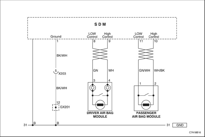
When the ignition switch is turned to the ON position, the sensing and diagnostic module (SDM) performs an initial check to detect significant problems within the SDM itself.
After these checks, the module measures the voltages in the ignition and airbag deployment circuits, verifying that they are within the nominal ranges. The SDM monitors the voltages in the driver and passenger airbag low-level wires, detecting a short to ground or supply voltage in the deployment circuits.
The SDM tests the wiring to the driver's front airbag deployment circuit by passing a tiny current through the internal circuit and checking for resistance.
- Resistance too high or too low - The resistance of the driver airbag deployment circuit is higher than 4.24 ohms or lower than 2.01 ohms.
- Breaking the chain - Break in the front driver airbag deployment circuit
- Short circuits to battery voltage or short circuits to ground - Short circuit to battery voltage or to ground in the front driver airbag deployment circuit.
Caution! The sensing and diagnostic module (SDM) can retain sufficient voltage to deploy the air bags and pretensioners for 1 minute after the ignition is turned off and the fuse is removed. If the air bags and pretensioners are not disconnected, do not begin servicing until one minute has passed after disconnecting power from the SDM. Failure to do so could result in personal injury.
Attention! Handle the Sensor and Diagnostic module (SDM) very carefully during maintenance. Do not hit or shake the SDM. Never connect power to the Airbag Inflator system (SIR) unless the SDM is rigidly connected to the vehicle. In order for the Airbag Inflator system (SIR) to work correctly, all the mounting bolts of the SDM sensor and diagnostic module must be carefully tightened, and the arrow on the SDM must point towards the front of the vehicle. If the SDM module is not firmly attached to the vehicle, the included module may trigger, causing the airbags to release unexpectedly and causing injury.
| Step | Operation | Values | Yes | No |
| 1 |
|
-
|
Proceed to Step 2
|
-
|
| 2 |
Inspect the driver's front airbag connector and wiring.
Is the connector disconnected?
|
-
|
Connect the connector and go to Step 1
|
Proceed to Step 3
|
| 3 |
Is the resistance close to 0 (zero)?
|
? 0 Ohm
|
Proceed to Step 4
|
Proceed to Step 5
|
| 4 |
Is the diagnostic trouble code cleared?
|
-
|
The system is normal.
|
Replace the driver's front airbag module.
|
| 5 |
Is the resistance close to 0 (zero)?
|
? 0 Ohm
|
Replace the clock spring.
|
Replace the airbag wiring.
|
Caution! The sensing and diagnostic module (SDM) can retain sufficient voltage to deploy the air bags and pretensioners for 1 minute after the ignition is turned off and the fuse is removed. If the air bags and pretensioners are not disconnected, do not begin servicing until one minute has passed after disconnecting power from the SDM. Failure to do so could result in personal injury.
Attention! Handle the Sensor and Diagnostic module (SDM) very carefully during maintenance. Do not hit or shake the SDM. Never connect power to the Airbag Inflator system (SIR) unless the SDM is rigidly connected to the vehicle. In order for the Airbag Inflator system (SIR) to work correctly, all the mounting bolts of the SDM sensor and diagnostic module must be carefully tightened, and the arrow on the SDM must point towards the front of the vehicle. If the SDM module is not firmly attached to the vehicle, the included module may trigger, causing the airbags to release unexpectedly and causing injury.
| Step | Operation | Values | Yes | No |
| 1 |
|
-
|
Proceed to Step 2
|
-
|
| 2 |
Inspect the driver's front airbag connector and wiring.
Is the airbag wiring damaged?
|
-
|
Replace the airbag wiring.
|
Proceed to Step 5
|
| 3 |
The resistance is??
|
?
|
Proceed to Step 4
|
Proceed to Step 5
|
| 4 |
Is the diagnostic trouble code cleared?
|
-
|
The system is normal.
|
Replace the driver's front airbag module.
|
| 5 |
The resistance is??
|
?
|
Replace the airbag wiring.
|
Replace the clock spring.
|
Caution! The sensing and diagnostic module (SDM) can retain sufficient voltage to deploy the air bags and pretensioners for 1 minute after the ignition is turned off and the fuse is removed. If the air bags and pretensioners are not disconnected, do not begin servicing until one minute has passed after disconnecting power from the SDM. Failure to do so could result in personal injury.
Attention! Handle the Sensor and Diagnostic module (SDM) very carefully during maintenance. Do not hit or shake the SDM. Never connect power to the Airbag Inflator system (SIR) unless the SDM is rigidly connected to the vehicle. In order for the Airbag Inflator system (SIR) to work correctly, all the mounting bolts of the SDM sensor and diagnostic module must be carefully tightened, and the arrow on the SDM must point towards the front of the vehicle. If the SDM module is not firmly attached to the vehicle, the included module may trigger, causing the airbags to release unexpectedly and causing injury.
| Step | Operation | Values | Yes | No |
| 1 |
|
-
|
Proceed to Step 2
|
-
|
| 2 |
Inspect the driver's front airbag connector and wiring.
Is the airbag wiring damaged?
|
-
|
Replace the airbag wiring.
|
Proceed to Step 3
|
| 3 |
Resistance above 50 kOhm?
|
50 Ohm
|
Proceed to Step 4
|
Proceed to Step 5
|
| 4 |
Is the diagnostic trouble code cleared?
|
-
|
The system is normal.
|
Replace the driver's front airbag module.
|
| 5 |
Resistance above 50 kOhm?
|
50 Ohm
|
Replace the clock spring.
|
Replace the airbag wiring.
|
Caution! The sensing and diagnostic module (SDM) can retain sufficient voltage to deploy the air bags and pretensioners for 1 minute after the ignition is turned off and the fuse is removed. If the air bags and pretensioners are not disconnected, do not begin servicing until one minute has passed after disconnecting power from the SDM. Failure to do so could result in personal injury.
Attention! Handle the Sensor and Diagnostic module (SDM) very carefully during maintenance. Do not hit or shake the SDM. Never connect power to the Airbag Inflator system (SIR) unless the SDM is rigidly connected to the vehicle. In order for the Airbag Inflator system (SIR) to work correctly, all the mounting bolts of the SDM sensor and diagnostic module must be carefully tightened, and the arrow on the SDM must point towards the front of the vehicle. If the SDM module is not firmly attached to the vehicle, the included module may trigger, causing the airbags to release unexpectedly and causing injury.
| Step | Operation | Values | Yes | No |
| 1 |
|
-
|
Proceed to Step 2
|
-
|
| 2 |
Inspect the driver's front airbag connector and wiring.
Is the airbag wiring damaged?
|
-
|
Replace the airbag wiring.
|
Proceed to Step 3
|
| 3 |
Resistance above 50 kOhm?
|
50 Ohm
|
Proceed to Step 4
|
Proceed to Step 5
|
| 4 |
Is the diagnostic trouble code cleared?
|
-
|
The system is normal.
|
Replace the driver's front airbag module.
|
| 5 |
Resistance above 50 kOhm?
|
50 Ohm
|
Replace the clock spring.
|
Replace the airbag wiring.
|
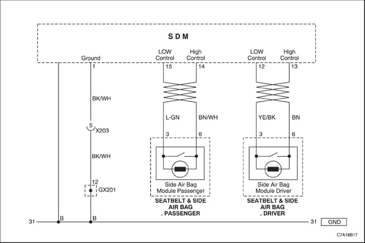
When the ignition switch is turned to the ON position, the sensing and diagnostic module (SDM) performs an initial check to detect significant problems within the SDM itself.
After these checks, the module measures the voltages in the ignition and airbag deployment circuits, verifying that they are within the nominal ranges. The SDM monitors the voltages in the driver and passenger airbag low-level wires, detecting a short to ground or supply voltage in the deployment circuits.
The SDM tests the wiring to the driver's side airbag deployment circuit by passing a tiny current through the internal circuit and checking for resistance.
- Resistance too high or too low - The resistance of the driver's side airbag deployment circuit is higher than 3.45 ohms or lower than 1.77 ohms.
- Breaking the chain - Break in the driver's side airbag deployment circuit.
- Short to battery voltage or short to ground - Short circuit to battery voltage or to ground in the driver's side airbag deployment circuit.
Code B0014 - "Resistance Too High" or "Open" in the Side Air Bag Deployment Circuit: Left Front/Driver
Caution! The sensing and diagnostic module (SDM) can retain sufficient voltage to deploy the air bags and pretensioners for 1 minute after the ignition is turned off and the fuse is removed. If the air bags and pretensioners are not disconnected, do not begin servicing until one minute has passed after disconnecting power from the SDM. Failure to do so could result in personal injury.
Attention! Handle the Sensor and Diagnostic module (SDM) very carefully during maintenance. Do not hit or shake the SDM. Never connect power to the Airbag Inflator system (SIR) unless the SDM is rigidly connected to the vehicle. In order for the Airbag Inflator system (SIR) to work correctly, all the mounting bolts of the SDM sensor and diagnostic module must be carefully tightened, and the arrow on the SDM must point towards the front of the vehicle. If the SDM module is not firmly attached to the vehicle, the included module may trigger, causing the airbags to release unexpectedly and causing injury.
| Step | Operation | Values | Yes | No |
| 1 |
Wait one minute to allow the sensing and diagnostic module power supply to discharge.
|
-
|
Proceed to Step 2
|
-
|
| 2 |
Inspect the driver's side airbag connector and wiring.
Is the connector disconnected?
|
-
|
Connect the connector and go to Step 1
|
Proceed to Step 3
|
| 3 |
Is the resistance close to 0 (zero)?
|
? 0 Ohm
|
Proceed to Step 4
|
Replace the airbag wiring.
|
| 4 |
Is the diagnostic trouble code cleared?
|
-
|
The system is normal.
|
Replace the driver's side airbag module.
|
Caution! The sensing and diagnostic module (SDM) can retain sufficient voltage to deploy the air bags and pretensioners for 1 minute after the ignition is turned off and the fuse is removed. If the air bags and pretensioners are not disconnected, do not begin servicing until one minute has passed after disconnecting power from the SDM. Failure to do so could result in personal injury.
Attention! Handle the Sensor and Diagnostic module (SDM) very carefully during maintenance. Do not hit or shake the SDM. Never connect power to the Airbag Inflator system (SIR) unless the SDM is rigidly connected to the vehicle. In order for the Airbag Inflator system (SIR) to work correctly, all the mounting bolts of the SDM sensor and diagnostic module must be carefully tightened, and the arrow on the SDM must point towards the front of the vehicle. If the SDM module is not firmly attached to the vehicle, the included module may trigger, causing the airbags to release unexpectedly and causing injury.
| Step | Operation | Values | Yes | No |
| 1 |
|
-
|
Proceed to Step 2
|
-
|
| 2 |
Inspect the driver's side airbag connector and wiring.
Is the airbag wiring damaged?
|
-
|
Replace the airbag wiring.
|
Proceed to Step 3
|
| 3 |
The resistance is??
|
?
|
Proceed to Step 4
|
Replace the airbag wiring.
|
| 4 |
Is the diagnostic trouble code cleared?
|
-
|
The system is normal.
|
Replace the driver's side airbag module.
|
Caution! The sensing and diagnostic module (SDM) can retain sufficient voltage to deploy the air bags and pretensioners for 1 minute after the ignition is turned off and the fuse is removed. If the air bags and pretensioners are not disconnected, do not begin servicing until one minute has passed after disconnecting power from the SDM. Failure to do so could result in personal injury.
Attention! Handle the Sensor and Diagnostic module (SDM) very carefully during maintenance. Do not hit or shake the SDM. Never connect power to the Airbag Inflator system (SIR) unless the SDM is rigidly connected to the vehicle. In order for the Airbag Inflator system (SIR) to work correctly, all the mounting bolts of the SDM sensor and diagnostic module must be carefully tightened, and the arrow on the SDM must point towards the front of the vehicle. If the SDM module is not firmly attached to the vehicle, the included module may trigger, causing the airbags to release unexpectedly and causing injury.
| Step | Operation | Values | Yes | No |
| 1 |
|
-
|
Proceed to Step 2
|
-
|
| 2 |
Inspect the driver's side airbag connector and wiring.
Is the airbag wiring damaged?
|
-
|
Replace the airbag wiring.
|
Proceed to Step 3
|
| 3 |
Resistance above 50 kOhm?
|
50 Ohm
|
Proceed to Step 4
|
Replace the airbag wiring.
|
| 4 |
Is the diagnostic trouble code cleared?
|
-
|
The system is normal.
|
Replace the driver's side airbag module.
|
Caution! The sensing and diagnostic module (SDM) can retain sufficient voltage to deploy the air bags and pretensioners for 1 minute after the ignition is turned off and the fuse is removed. If the air bags and pretensioners are not disconnected, do not begin servicing until one minute has passed after disconnecting power from the SDM. Failure to do so could result in personal injury.
Attention! Handle the Sensor and Diagnostic module (SDM) very carefully during maintenance. Do not hit or shake the SDM. Never connect power to the Airbag Inflator system (SIR) unless the SDM is rigidly connected to the vehicle. In order for the Airbag Inflator system (SIR) to work properly, all the mounting bolts of the SDM sensor and diagnostic module must be carefully tightened, and the arrow on the SDM module must point towards the front of the vehicle. If the SDM module is not firmly attached to the vehicle, the included module may trigger, causing the airbags to release unexpectedly and causing injury.
| Step | Operation | Values | Yes | No |
| 1 |
|
-
|
Proceed to Step 2
|
-
|
| 2 |
Inspect the driver's side airbag connector and wiring.
Is the airbag wiring damaged?
|
-
|
Replace the airbag wiring.
|
Proceed to Step 3
|
| 3 |
Resistance above 50 kOhm?
|
50 Ohm
|
Proceed to Step 4
|
Replace the airbag wiring.
|
| 4 |
Is the diagnostic trouble code cleared?
|
-
|
The system is normal.
|
Replace the driver's side airbag module.
|
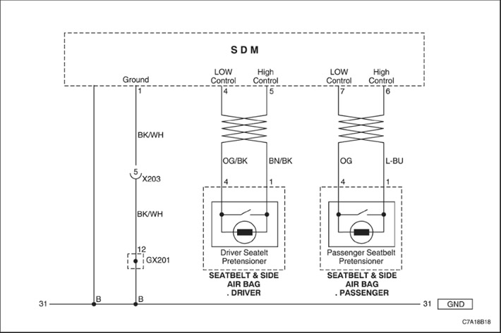
When the ignition switch is turned to the ON position, the sensing and diagnostic module (SDM) performs an initial check to detect significant problems within the SDM itself.
After these checks, the module measures the voltages in the ignition and airbag deployment circuits, verifying that they are within the nominal ranges. The SDM monitors the voltages in the driver and passenger airbag low-level wires, detecting a short to ground or supply voltage in the deployment circuits.
The SDM tests the wiring to the driver's seat belt pretensioner deployment circuit by passing a tiny current through the internal circuit and checking for resistance.
- Resistance too high or too low - The resistance of the driver's seat belt pretensioner trigger circuit is greater than 3.54 ohms or less than 1.77 ohms.
- Breaking the chain - Open circuit of the driver's seat belt tensioner.
- Short to battery voltage or short to ground - Short circuit to battery voltage or to ground in the driver's seat belt tensioner circuit.
Code B0015 - Seat Belt Pretensioner Activation Circuit "Too High Resistance" or "Open": Left Front/Driver
Caution! The sensing and diagnostic module (SDM) can retain sufficient voltage to deploy the air bags and pretensioners for 1 minute after the ignition is turned off and the fuse is removed. If the air bags and pretensioners are not disconnected, do not begin servicing until one minute has passed after disconnecting power from the SDM. Failure to do so could result in personal injury.
Attention! Handle the Sensor and Diagnostic module (SDM) very carefully during maintenance. Do not hit or shake the SDM. Never connect power to the Airbag Inflator system (SIR) unless the SDM is rigidly connected to the vehicle. In order for the Airbag Inflator system (SIR) to work properly, all the mounting bolts of the SDM sensor and diagnostic module must be carefully tightened, and the arrow on the SDM module must point towards the front of the vehicle. If the SDM module is not firmly attached to the vehicle, the included module may trigger, causing the airbags to release unexpectedly and causing injury.
| Step | Operation | Values | Yes | No |
| 1 |
|
-
|
Proceed to Step 2
|
-
|
| 2 |
Inspect the driver's seat belt pretensioner connector and wiring.
Is the connector disconnected?
|
-
|
Connect the connector and go to Step 1
|
Proceed to Step 3
|
| 3 |
Is the resistance close to 0 (zero)?
|
? 0 Ohm
|
Proceed to Step 4
|
Replace the airbag wiring.
|
| 4 |
Is the diagnostic trouble code cleared?
|
-
|
The system is normal.
|
Replace the driver's seat belt tensioner.
|
Caution! The sensing and diagnostic module (SDM) can retain sufficient voltage to deploy the air bags and pretensioners for 1 minute after the ignition is turned off and the fuse is removed. If the air bags and pretensioners are not disconnected, do not begin servicing until one minute has passed after disconnecting power from the SDM. Failure to do so could result in personal injury.
Attention! Handle the Sensor and Diagnostic module (SDM) very carefully during maintenance. Do not hit or shake the SDM. Never connect power to the Airbag Inflator system (SIR) unless the SDM is rigidly connected to the vehicle. In order for the Airbag Inflator system (SIR) to work correctly, all the mounting bolts of the SDM sensor and diagnostic module must be carefully tightened, and the arrow on the SDM must point towards the front of the vehicle. If the SDM module is not firmly attached to the vehicle, the included module may trigger, causing the airbags to release unexpectedly and causing injury.
| Step | Operation | Values | Yes | No |
| 1 |
|
-
|
Proceed to Step 2
|
-
|
| 2 |
Inspect the driver's seat belt pretensioner connector and wiring.
Is the wiring damaged?
|
-
|
Replace the airbag wiring.
|
Proceed to Step 3
|
| 3 |
The resistance is??
|
?
|
Proceed to Step 4
|
Replace the airbag wiring.
|
| 4 |
Is the diagnostic trouble code cleared?
|
-
|
The system is normal.
|
Replace the driver's seat belt tensioner.
|
Caution! The sensing and diagnostic module (SDM) can retain sufficient voltage to deploy the air bags and pretensioners for 1 minute after the ignition is turned off and the fuse is removed. If the air bags and pretensioners are not disconnected, do not begin servicing until one minute has passed after disconnecting power from the SDM. Failure to do so could result in personal injury.
Attention! Handle the Sensor and Diagnostic module (SDM) very carefully during maintenance. Do not hit or shake the SDM. Never connect power to the Airbag Inflator system (SIR) unless the SDM is rigidly connected to the vehicle. In order for the Airbag Inflator system (SIR) to work correctly, all the mounting bolts of the SDM sensor and diagnostic module must be carefully tightened, and the arrow on the SDM must point towards the front of the vehicle. If the SDM module is not firmly attached to the vehicle, the included module may trigger, causing the airbags to release unexpectedly and causing injury.
| Step | Operation | Values | Yes | No |
| 1 |
|
-
|
Proceed to Step 2
|
-
|
| 2 |
Inspect the driver's seat belt pretensioner connector and wiring.
Is the wiring damaged?
|
-
|
Replace the airbag wiring.
|
Proceed to Step 3
|
| 3 |
Resistance above 50 kOhm?
|
50 Ohm
|
Proceed to Step 4
|
Replace the airbag wiring.
|
| 4 |
Is the diagnostic trouble code cleared?
|
-
|
The system is normal.
|
Replace the driver's seat belt tensioner.
|
Caution! The sensing and diagnostic module (SDM) can retain sufficient voltage to deploy the air bags and pretensioners for 1 minute after the ignition is turned off and the fuse is removed. If the air bags and pretensioners are not disconnected, do not begin servicing until one minute has passed after disconnecting power from the SDM. Failure to do so could result in personal injury.
Attention! Handle the Sensor and Diagnostic module (SDM) very carefully during maintenance. Do not hit or shake the SDM. Never connect power to the Airbag Inflator system (SIR) unless the SDM is rigidly connected to the vehicle. In order for the Airbag Inflator system (SIR) to work correctly, all the mounting bolts of the SDM sensor and diagnostic module must be carefully tightened, and the arrow on the SDM must point towards the front of the vehicle. If the SDM module is not firmly attached to the vehicle, the included module may trigger, causing the airbags to release unexpectedly and causing injury.
| Step | Operation | Values | Yes | No |
| 1 |
|
-
|
Proceed to Step 2
|
-
|
| 2 |
Inspect the driver's seat belt pretensioner connector and wiring.
Is the wiring damaged?
|
-
|
Replace the airbag wiring.
|
Proceed to Step 3
|
| 3 |
Resistance above 50 kOhm?
|
50 Ohm
|
Proceed to Step 4
|
Replace the airbag wiring.
|
| 4 |
Is the diagnostic trouble code cleared?
|
-
|
The system is normal.
|
Replace the driver's seat belt tensioner.
|
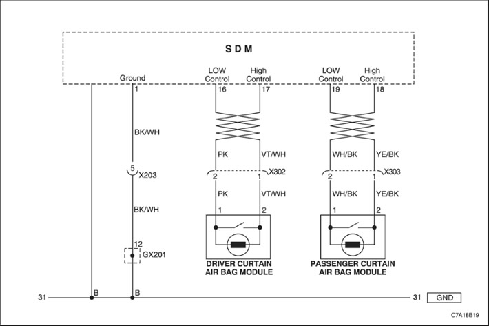
When the ignition switch is turned to the ON position, the sensing and diagnostic module (SDM) performs an initial check to detect significant problems within the SDM itself.
After these checks, the module measures the voltages in the ignition and airbag deployment circuits, verifying that they are within the nominal ranges. The SDM monitors the voltages in the driver and passenger airbag low-level wires, detecting a short to ground or supply voltage in the deployment circuits.
The SDM tests the wiring to the driver's head curtain airbag deployment circuit by passing a tiny current through the internal circuit and checking for resistance.
- Resistance too high or too low - The resistance of the driver's head curtain airbag deployment circuit is higher than 3.54 ohms or lower than 1.77 ohms.
- Breaking the chain - Break in the driver's head curtain activation circuit.
- Short to battery voltage or short to ground - Short circuit to battery voltage or to ground in the driver's head curtain actuation circuit.
Code B0016 - "Resistance Too High" or "Open" in the Air Bag Deployment Circuit: Left Front/Driver, Roof Rail/Head Curtain
Caution! The sensing and diagnostic module (SDM) can retain sufficient voltage to deploy the air bags and pretensioners for 1 minute after the ignition is turned off and the fuse is removed. If the air bags and pretensioners are not disconnected, do not begin servicing until one minute has passed after disconnecting power from the SDM. Failure to do so could result in personal injury.
Attention! Handle the Sensor and Diagnostic module (SDM) very carefully during maintenance. Do not hit or shake the SDM. Never connect power to the Airbag Inflator system (SIR) unless the SDM is rigidly connected to the vehicle. In order for the Airbag Inflator system (SIR) to work correctly, all the mounting bolts of the SDM sensor and diagnostic module must be carefully tightened, and the arrow on the SDM must point towards the front of the vehicle. If the SDM module is not firmly attached to the vehicle, the included module may trigger, causing the airbags to release unexpectedly and causing injury.
| Step | Operation | Values | Yes | No |
| 1 |
|
-
|
Proceed to Step 2
|
-
|
| 2 |
Inspect the connector and wiring of the driver's head curtain airbag.
Is the connector disconnected?
|
-
|
Connect the connector and go to Step 1
|
Proceed to Step 3
|
| 3 |
Is the resistance close to 0 (zero)?
|
? 0 Ohm
|
Proceed to Step 4
|
Replace the airbag wiring.
|
| 4 |
Is the diagnostic trouble code cleared?
|
-
|
The system is normal.
|
Replace the driver's head curtain airbag module.
|
Code B0016 - "Resistance too low" of the airbag deployment circuit: left front / driver, roof rail / curtain head
Caution! The sensing and diagnostic module (SDM) can retain sufficient voltage to deploy the air bags and pretensioners for 1 minute after the ignition is turned off and the fuse is removed. If the air bags and pretensioners are not disconnected, do not begin servicing until one minute has passed after disconnecting power from the SDM. Failure to do so could result in personal injury.
Attention! Handle the Sensor and Diagnostic module (SDM) very carefully during maintenance. Do not hit or shake the SDM. Never connect power to the Airbag Inflator system (SIR) unless the SDM is rigidly connected to the vehicle. In order for the Airbag Inflator system (SIR) to work correctly, all the mounting bolts of the SDM sensor and diagnostic module must be carefully tightened, and the arrow on the SDM must point towards the front of the vehicle. If the SDM module is not firmly attached to the vehicle, the included module may trigger, causing the airbags to release unexpectedly and causing injury.
| Step | Operation | Values | Yes | No |
| 1 |
|
-
|
Proceed to Step 1
|
-
|
| 2 |
Inspect the connector and wiring of the driver's head curtain airbag.
Is the wiring damaged?
|
-
|
Replace the airbag wiring.
|
Proceed to Step 3
|
| 3 |
The resistance is??
|
?
|
Proceed to Step 4
|
Replace the airbag wiring.
|
| 4 |
Is the diagnostic trouble code cleared?
|
-
|
The system is normal.
|
Replace the driver's head curtain airbag module.
|
Code B0016 - "Short to ground" of the airbag deployment circuit: left front / driver, roof rail / head curtain
Caution! The sensing and diagnostic module (SDM) can retain sufficient voltage to deploy the air bags and pretensioners for 1 minute after the ignition is turned off and the fuse is removed. If the air bags and pretensioners are not disconnected, do not begin servicing until one minute has passed after disconnecting power from the SDM. Failure to do so could result in personal injury.
Attention! Handle the Sensor and Diagnostic module (SDM) very carefully during maintenance. Do not hit or shake the SDM. Never connect power to the Airbag Inflator system (SIR) unless the SDM is rigidly connected to the vehicle. In order for the Airbag Inflator system (SIR) to work correctly, all the mounting bolts of the SDM sensor and diagnostic module must be carefully tightened, and the arrow on the SDM must point towards the front of the vehicle. If the SDM module is not firmly attached to the vehicle, the included module may trigger, causing the airbags to release unexpectedly and causing injury.
| Step | Operation | Values | Yes | No |
| 1 |
|
-
|
Proceed to Step 2
|
-
|
| 2 |
Inspect the driver head curtain airbag module connector and wiring.
Is the wiring damaged?
|
-
|
Replace the airbag wiring.
|
Proceed to Step 3
|
| 3 |
Resistance above 50 kOhm?
|
50 Ohm
|
Proceed to Step 4
|
Replace the airbag wiring.
|
| 4 |
Is the diagnostic trouble code cleared?
|
-
|
The system is normal.
|
Replace the driver's head curtain airbag module.
|
Code B0016 - "Short to Battery Voltage" in the Air Bag Deployment Circuit: Left Front/Driver, Roof Rail/Head Curtain
Caution! The sensing and diagnostic module (SDM) can retain sufficient voltage to deploy the air bags and pretensioners for 1 minute after the ignition is turned off and the fuse is removed. If the air bags and pretensioners are not disconnected, do not begin servicing until one minute has passed after disconnecting power from the SDM. Failure to do so could result in personal injury.
Attention! Handle the Sensor and Diagnostic module (SDM) very carefully during maintenance. Do not hit or shake the SDM. Never connect power to the Airbag Inflator system (SIR) unless the SDM is rigidly connected to the vehicle. In order for the Airbag Inflator system (SIR) to work correctly, all the mounting bolts of the SDM sensor and diagnostic module must be carefully tightened, and the arrow on the SDM must point towards the front of the vehicle. If the SDM module is not firmly attached to the vehicle, the included module may trigger, causing the airbags to release unexpectedly and causing injury.
| Step | Operation | Values | Yes | No |
| 1 |
|
-
|
Proceed to Step 2
|
-
|
| 2 |
Inspect the driver head curtain airbag module connector and wiring.
Is the wiring damaged?
|
-
|
Replace the airbag wiring.
|
Proceed to Step 3
|
| 3 |
Resistance above 50 kOhm?
|
50 Ohm
|
Proceed to Step 4
|
Replace the airbag wiring.
|
| 4 |
Is the diagnostic trouble code cleared?
|
-
|
The system is normal.
|
Replace the driver's head curtain airbag module.
|
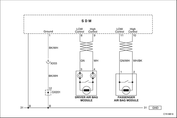
When the ignition switch is turned to the ON position, the sensing and diagnostic module (SDM) performs an initial check to detect significant problems within the SDM itself.
After these checks, the module measures the voltages in the ignition and airbag deployment circuits, verifying that they are within the nominal ranges. The SDM monitors the voltages in the driver and passenger airbag low-level wires, detecting a short to ground or supply voltage in the deployment circuits.
The SDM tests the wiring to the passenger front airbag deployment circuit by passing a tiny current through the internal circuit and checking for resistance.
- Resistance too high or too low - The resistance of the front passenger airbag deployment circuit is greater than 3.54 ohms or lower than 1.77 ohms.
- Breaking the chain - Front passenger airbag deployment circuit high and low wires.
- Short to battery voltage or short to ground - Short circuit to battery voltage or to ground in the front passenger airbag deployment circuit.
Code B0019 - "Resistance Too High" or "Open" Front Air Bag Deployment Circuit: Right Front/Passenger
Caution! The sensing and diagnostic module (SDM) can retain sufficient voltage to deploy the air bags and pretensioners for 1 minute after the ignition is turned off and the fuse is removed. If the air bags and pretensioners are not disconnected, do not begin servicing until one minute has passed after disconnecting power from the SDM. Failure to do so could result in personal injury.
Attention! Handle the Sensor and Diagnostic module (SDM) very carefully during maintenance. Do not hit or shake the SDM. Never connect power to the Airbag Inflator system (SIR) unless the SDM is rigidly connected to the vehicle. In order for the Airbag Inflator system (SIR) to work correctly, all the mounting bolts of the SDM sensor and diagnostic module must be carefully tightened, and the arrow on the SDM must point towards the front of the vehicle. If the SDM module is not firmly attached to the vehicle, the included module may trigger, causing the airbags to release unexpectedly and causing injury.
| Step | Operation | Values | Yes | No |
| 1 |
Wait one minute to allow the sensing and diagnostic module power supply to discharge.
|
-
|
Proceed to Step 2
|
-
|
| 2 |
Inspect the front passenger airbag connector and wiring.
Is the connector disconnected?
|
-
|
Connect the connector and go to Step 1
|
Proceed to Step 3
|
| 3 |
Is the resistance close to 0 (zero)?
|
? 0 Ohm
|
Proceed to Step 4
|
Replace the airbag wiring.
|
| 4 |
Is the diagnostic trouble code cleared?
|
-
|
The system is normal.
|
Replace the passenger front air bag module.
|
Caution! The sensing and diagnostic module (SDM) can retain sufficient voltage to deploy the air bags and pretensioners for 1 minute after the ignition is turned off and the fuse is removed. If the air bags and pretensioners are not disconnected, do not begin servicing until one minute has passed after disconnecting power from the SDM. Failure to do so could result in personal injury.
Attention! Handle the Sensor and Diagnostic module (SDM) very carefully during maintenance. Do not hit or shake the SDM. Never connect power to the Airbag Inflator system (SIR) unless the SDM is rigidly connected to the vehicle. In order for the Airbag Inflator system (SIR) to work correctly, all the mounting bolts of the SDM sensor and diagnostic module must be carefully tightened, and the arrow on the SDM must point towards the front of the vehicle. If the SDM module is not firmly attached to the vehicle, the included module may trigger, causing the airbags to release unexpectedly and causing injury.
| Step | Operation | Values | Yes | No |
| 1 |
|
-
|
Proceed to Step 2
|
-
|
| 2 |
Inspect the front passenger airbag connector and wiring.
Is the airbag wiring damaged?
|
-
|
Replace the airbag wiring.
|
Proceed to Step 3
|
| 3 |
The resistance is??
|
?
|
Proceed to Step 4
|
Replace the airbag wiring.
|
| 4 |
Is the diagnostic trouble code cleared?
|
-
|
The system is normal.
|
Replace the passenger front air bag module.
|
Caution! The sensing and diagnostic module (SDM) can retain sufficient voltage to deploy the air bags and pretensioners for 1 minute after the ignition is turned off and the fuse is removed. If the air bags and pretensioners are not disconnected, do not begin servicing until one minute has passed after disconnecting power from the SDM. Failure to do so could result in personal injury.
Attention! Handle the Sensor and Diagnostic module (SDM) very carefully during maintenance. Do not hit or shake the SDM. Never connect power to the Airbag Inflator system (SIR) unless the SDM is rigidly connected to the vehicle. In order for the Airbag Inflator system (SIR) to work correctly, all the mounting bolts of the SDM sensor and diagnostic module must be carefully tightened, and the arrow on the SDM must point towards the front of the vehicle. If the SDM module is not firmly attached to the vehicle, the included module may trigger, causing the airbags to release unexpectedly and causing injury.
| Step | Operation | Values | Yes | No |
| 1 |
|
-
|
Proceed to Step 2
|
-
|
| 2 |
Inspect the front passenger airbag connector and wiring.
Is the wiring damaged?
|
-
|
Replace the airbag wiring.
|
Proceed to Step 3
|
| 3 |
Resistance above 50 kOhm?
|
50 Ohm
|
Proceed to Step 4
|
Replace the airbag wiring.
|
| 4 |
Is the diagnostic trouble code cleared?
|
-
|
The system is normal.
|
Replace the passenger front air bag module.
|
Caution! The sensing and diagnostic module (SDM) can retain sufficient voltage to deploy the air bags and pretensioners for 1 minute after the ignition is turned off and the fuse is removed. If the air bags and pretensioners are not disconnected, do not begin servicing until one minute has passed after disconnecting power from the SDM. Failure to do so could result in personal injury.
Attention! Handle the Sensor and Diagnostic module (SDM) very carefully during maintenance. Do not hit or shake the SDM. Never connect power to the Airbag Inflator system (SIR) unless the SDM is rigidly connected to the vehicle. In order for the Airbag Inflator system (SIR) to work correctly, all the mounting bolts of the SDM sensor and diagnostic module must be carefully tightened, and the arrow on the SDM must point towards the front of the vehicle. If the SDM module is not firmly attached to the vehicle, the included module may trigger, causing the airbags to release unexpectedly and causing injury.
| Step | Operation | Values | Yes | No |
| 1 |
|
-
|
Proceed to Step 2
|
-
|
| 2 |
Inspect the front passenger airbag connector and wiring.
Is the wiring damaged?
|
-
|
Replace the airbag wiring.
|
Proceed to Step 3
|
| 3 |
Resistance above 50 kOhm?
|
50 Ohm
|
Proceed to Step 4
|
Replace the airbag wiring.
|
| 4 |
Is the diagnostic trouble code cleared?
|
-
|
The system is normal.
|
Replace the passenger front air bag module.
|
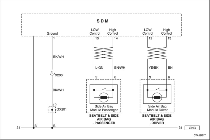
When the ignition switch is turned to the ON position, the sensing and diagnostic module (SDM) performs an initial check to detect significant problems within the SDM itself.
Following these tests, the module measures the voltages in the ignition and airbag deployment circuits, verifying that they are within the specified ranges. The SDM monitors the voltages in the driver and passenger airbag low-level wiring, detecting shorts in the deployment circuits to ground or supply voltage. The SDM tests the wiring to the passenger side airbag deployment circuit by passing a tiny current through the internal circuit and checking for resistance.
- Resistance too high or too low - The resistance of the passenger side airbag deployment circuit is higher than 3.54 ohms or lower than 1.77 ohms.
- Breaking the chain - High and low level wires of the passenger side airbag deployment circuit.
- Short to battery voltage or short to ground - Short circuit to battery voltage or to ground in the passenger airbag trigger circuit.
Code B0021 - "Resistance Too High" or "Open" in the Side Air Bag Deployment Circuit: Right Front/Passenger
Caution! The sensing and diagnostic module (SDM) can retain sufficient voltage to deploy the air bags and pretensioners for 1 minute after the ignition is turned off and the fuse is removed. If the air bags and pretensioners are not disconnected, do not begin servicing until one minute has passed after disconnecting power from the SDM. Failure to do so could result in personal injury.
Attention! Handle the Sensor and Diagnostic module (SDM) very carefully during maintenance. Do not hit or shake the SDM. Never connect power to the Airbag Inflator system (SIR) unless the SDM is rigidly connected to the vehicle. In order for the Airbag Inflator system (SIR) to work correctly, all the mounting bolts of the SDM sensor and diagnostic module must be carefully tightened, and the arrow on the SDM must point towards the front of the vehicle. If the SDM module is not firmly attached to the vehicle, the included module may trigger, causing the airbags to release unexpectedly and causing injury.
| Step | Operation | Values | Yes | No |
| 1 |
|
-
|
Proceed to Step 2
|
-
|
| 2 |
Inspect the passenger side airbag connector and wiring.
Is the connector disconnected?
|
-
|
Connect the connector and go to Step 1
|
Proceed to Step 3
|
| 3 |
Is the resistance close to 0 (zero)?
|
? 0 Ohm
|
Proceed to Step 4
|
Replace the airbag wiring.
|
| 4 |
Is the diagnostic trouble code cleared?
|
-
|
The system is normal.
|
Replace the passenger side airbag module.
|
Caution! The sensing and diagnostic module (SDM) can retain sufficient voltage to deploy the air bags and pretensioners for 1 minute after the ignition is turned off and the fuse is removed. If the air bags and pretensioners are not disconnected, do not begin servicing until one minute has passed after disconnecting power from the SDM. Failure to do so could result in personal injury.
Attention! Handle the Sensor and Diagnostic module (SDM) very carefully during maintenance. Do not hit or shake the SDM. Never connect power to the Airbag Inflator system (SIR) unless the SDM is rigidly connected to the vehicle. In order for the Airbag Inflator system (SIR) to work correctly, all the mounting bolts of the SDM sensor and diagnostic module must be carefully tightened, and the arrow on the SDM must point towards the front of the vehicle. If the SDM module is not firmly attached to the vehicle, the included module may trigger, causing the airbags to release unexpectedly and causing injury.
| Step | Operation | Values | Yes | No |
| 1 |
|
-
|
Proceed to Step 2
|
-
|
| 2 |
Inspect the passenger side airbag connector and wiring.
Is the wiring damaged?
|
-
|
Replace the airbag wiring.
|
Proceed to Step 3
|
| 3 |
The resistance is??
|
?
|
Proceed to Step 4
|
Replace the airbag wiring.
|
| 4 |
Is the diagnostic trouble code cleared?
|
-
|
Proceed to Step 4
|
Replace the passenger side airbag module.
|
Caution! The sensing and diagnostic module (SDM) can retain sufficient voltage to deploy the air bags and pretensioners for 1 minute after the ignition is turned off and the fuse is removed. If the air bags and pretensioners are not disconnected, do not begin servicing until one minute has passed after disconnecting power from the SDM. Failure to do so could result in personal injury.
Attention! Handle the Sensor and Diagnostic module (SDM) very carefully during maintenance. Do not hit or shake the SDM. Never connect power to the Airbag Inflator system (SIR) unless the SDM is rigidly connected to the vehicle. In order for the Airbag Inflator system (SIR) to work correctly, all the mounting bolts of the SDM sensor and diagnostic module must be carefully tightened, and the arrow on the SDM must point towards the front of the vehicle. If the SDM module is not firmly attached to the vehicle, the included module may trigger, causing the airbags to release unexpectedly and causing injury.
| Step | Operation | Values | Yes | No |
| 1 |
|
-
|
Proceed to Step 2
|
-
|
| 2 |
Inspect the passenger side airbag connector and wiring.
Is the wiring damaged?
|
-
|
Replace the airbag wiring.
|
Proceed to Step 3
|
| 3 |
Resistance above 50 kOhm?
|
50 Ohm
|
Proceed to Step 4
|
Replace the airbag wiring.
|
| 4 |
Is the diagnostic trouble code cleared?
|
-
|
The system is normal.
|
Replace the passenger side airbag module.
|
Caution! The sensing and diagnostic module (SDM) can retain sufficient voltage to deploy the air bags and pretensioners for 1 minute after the ignition is turned off and the fuse is removed. If the air bags and pretensioners are not disconnected, do not begin servicing until one minute has passed after disconnecting power from the SDM. Failure to do so could result in personal injury.
Attention! Handle the Sensor and Diagnostic module (SDM) very carefully during maintenance. Do not hit or shake the SDM. Never connect power to the Airbag Inflator system (SIR) unless the SDM is rigidly connected to the vehicle. In order for the Airbag Inflator system (SIR) to work correctly, all the mounting bolts of the SDM sensor and diagnostic module must be carefully tightened, and the arrow on the SDM must point towards the front of the vehicle. If the SDM module is not firmly attached to the vehicle, the included module may trigger, causing the airbags to release unexpectedly and causing injury.
| Step | Operation | Values | Yes | No |
| 1 |
|
-
|
Go to Step 2
|
-
|
| 2 |
Inspect the passenger side airbag connector and wiring.
Is the wiring damaged?
|
-
|
Replace the airbag wiring.
|
Proceed to Step 3
|
| 3 |
Resistance above 50 kOhm?
|
50 Ohm
|
Proceed to Step 4
|
Replace the airbag wiring.
|
| 4 |
Is the diagnostic trouble code cleared?
|
-
|
The system is normal.
|
Replace the passenger side airbag module.
|
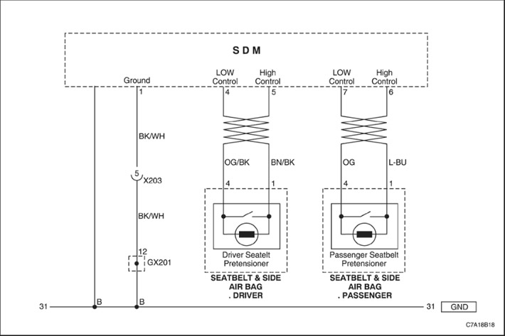
When the ignition switch is turned to the ON position, the sensing and diagnostic module (SDM) performs an initial check to detect significant problems within the SDM itself.
After these checks, the module measures the voltages in the ignition and airbag deployment circuits, verifying that they are within the nominal ranges. The SDM monitors the voltages in the driver and passenger airbag low-level wires, detecting a short to ground or supply voltage in the deployment circuits.
The SDM tests the wiring to the passenger seat belt pretensioner deployment circuit by passing a tiny current through the internal circuit and checking for resistance.
- Resistance too high or too low - The resistance of the passenger seat belt pretensioner circuit is greater than 3.54 ohms or less than 1.77 ohms.
- Breaking the chain - High and low level wires of the passenger seat belt tensioner actuation circuit.
- Short to battery voltage or short to ground - Short circuit to battery voltage or to ground in the passenger seat belt tensioner actuation circuit.
Code B0022 - "Resistance Too High" or "Open" in the Pretensioner Deployment Circuit: Right Front/Passenger
Caution! The sensing and diagnostic module (SDM) can retain sufficient voltage to deploy the air bags and pretensioners for 1 minute after the ignition is turned off and the fuse is removed. If the air bags and pretensioners are not disconnected, do not begin servicing until one minute has passed after disconnecting power from the SDM. Failure to do so could result in personal injury.
Attention! Handle the Sensor and Diagnostic module (SDM) very carefully during maintenance. Do not hit or shake the SDM. Never connect power to the Airbag Inflator system (SIR) unless the SDM is rigidly connected to the vehicle. In order for the Airbag Inflator system (SIR) to work correctly, all the mounting bolts of the SDM sensor and diagnostic module must be carefully tightened, and the arrow on the SDM must point towards the front of the vehicle. If the SDM module is not firmly attached to the vehicle, the included module may trigger, causing the airbags to release unexpectedly and causing injury.
| Step | Operation | Values | Yes | No |
| 1 |
|
-
|
Proceed to Step 2
|
-
|
| 2 |
Inspect the passenger seat belt pretensioner connector and wiring.
Is the connector disconnected?
|
-
|
Connect the connector and go to Step 1
|
Proceed to Step 3
|
| 3 |
Is the resistance close to 0 (zero)?
|
? 0 Ohm
|
Proceed to Step 4
|
Replace the airbag wiring.
|
| 4 |
Is the diagnostic trouble code cleared?
|
-
|
The system is normal.
|
Replace the passenger seat belt tensioner.
|
Code B0022 - "Resistance too low" of the trigger circuit of the pretensioners: right front / passenger
Caution! The sensing and diagnostic module (SDM) can retain sufficient voltage to deploy the air bags and pretensioners for 1 minute after the ignition is turned off and the fuse is removed. If the air bags and pretensioners are not disconnected, do not begin servicing until one minute has passed after disconnecting power from the SDM. Failure to do so could result in personal injury.
Attention! Handle the Sensor and Diagnostic module (SDM) very carefully during maintenance. Do not hit or shake the SDM. Never connect power to the Airbag Inflator system (SIR) unless the SDM is rigidly connected to the vehicle. In order for the Airbag Inflator system (SIR) to work correctly, all the mounting bolts of the SDM sensor and diagnostic module must be carefully tightened, and the arrow on the SDM must point towards the front of the vehicle. If the SDM module is not firmly attached to the vehicle, the included module may trigger, causing the airbags to release unexpectedly and causing injury.
| Step | Operation | Values | Yes | No |
| 1 |
|
-
|
Proceed to Step 1
|
-
|
| 2 |
Inspect the passenger seat belt pretensioner connector and wiring.
Is the wiring damaged?
|
-
|
Replace the airbag wiring.
|
Proceed to Step 3
|
| 3 |
The resistance is??
|
?
|
Proceed to Step 4
|
Replace the airbag wiring.
|
| 4 |
Is the diagnostic trouble code cleared?
|
-
|
The system is normal.
|
Replace the passenger seat belt tensioner.
|
Caution! The sensing and diagnostic module (SDM) can retain sufficient voltage to deploy the air bags and pretensioners for 1 minute after the ignition is turned off and the fuse is removed. If the air bags and pretensioners are not disconnected, do not begin servicing until one minute has passed after disconnecting power from the SDM. Failure to do so could result in personal injury.
Attention! Handle the Sensor and Diagnostic module (SDM) very carefully during maintenance. Do not hit or shake the SDM. Never connect power to the Airbag Inflator system (SIR) unless the SDM is rigidly connected to the vehicle. In order for the Airbag Inflator system (SIR) to work correctly, all the mounting bolts of the SDM sensor and diagnostic module must be carefully tightened, and the arrow on the SDM must point towards the front of the vehicle. If the SDM module is not firmly attached to the vehicle, the included module may trigger, causing the airbags to release unexpectedly and causing injury.
| Step | Operation | Values | Yes | No |
| 1 |
|
-
|
Proceed to Step 2
|
-
|
| 2 |
Inspect the passenger seat belt pretensioner connector and wiring.
Is the wiring damaged?
|
-
|
Replace the airbag wiring.
|
Proceed to Step 3
|
| 3 |
Resistance above 50 kOhm?
|
50 Ohm
|
Proceed to Step 4
|
Replace the airbag wiring.
|
| 4 |
Is the diagnostic trouble code cleared?
|
-
|
The system is normal.
|
Replace the passenger seat belt tensioner.
|
Caution! The sensing and diagnostic module (SDM) can retain sufficient voltage to deploy the air bags and pretensioners for 1 minute after the ignition is turned off and the fuse is removed. If the air bags and pretensioners are not disconnected, do not begin servicing until one minute has passed after disconnecting power from the SDM. Failure to do so could result in personal injury.
Attention! Handle the Sensor and Diagnostic module (SDM) very carefully during maintenance. Do not hit or shake the SDM. Never connect power to the Airbag Inflator system (SIR) unless the SDM is rigidly connected to the vehicle. In order for the Airbag Inflator system (SIR) to work correctly, all the mounting bolts of the SDM sensor and diagnostic module must be carefully tightened, and the arrow on the SDM must point towards the front of the vehicle. If the SDM module is not firmly attached to the vehicle, the included module may trigger, causing the airbags to release unexpectedly and causing injury.
| Step | Operation | Values | Yes | No |
| 1 |
|
-
|
Proceed to Step 2
|
-
|
| 2 |
Inspect the passenger seat belt pretensioner connector and wiring.
Is the wiring damaged?
|
-
|
Replace the airbag wiring.
|
Proceed to Step 3
|
| 3 |
Resistance above 50 kOhm?
|
50 Ohm
|
Proceed to Step 4
|
Replace the airbag wiring.
|
| 4 |
Is the diagnostic trouble code cleared?
|
-
|
The system is normal.
|
Replace the passenger seat belt tensioner.
|
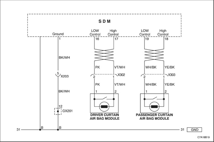
When the ignition switch is turned to the ON position, the sensing and diagnostic module (SDM) performs an initial check to detect significant problems within the SDM itself.
After these checks, the module measures the voltages in the ignition and airbag deployment circuits, verifying that they are within the nominal ranges. The SDM monitors the voltages in the driver and passenger airbag low-level wires, detecting a short to ground or supply voltage in the deployment circuits.
The SDM tests the wiring to the passenger head curtain airbag deployment circuit by passing a tiny current through the internal circuit and checking for resistance.
- Resistance too high or too low - The resistance of the passenger head curtain airbag deployment circuit is higher than 3.54 ohms or lower than 1.77 ohms.
- Breaking the chain - Upper and lower level wires of the passenger head curtain actuation circuit.
- Short to battery voltage or short to ground - Short circuit to battery voltage or to ground in the passenger head curtain actuation circuit.
Code B0023 - "Resistance Too High" or "Open" in the Air Bag Deployment Circuit: Right Front/Passenger, Roof Rail/Head Curtain
Caution! The sensing and diagnostic module (SDM) can retain sufficient voltage to deploy the air bags and pretensioners for 1 minute after the ignition is turned off and the fuse is removed. If the air bags and pretensioners are not disconnected, do not begin servicing until one minute has passed after disconnecting power from the SDM. Failure to do so could result in personal injury.
Attention! Handle the Sensor and Diagnostic module (SDM) very carefully during maintenance. Do not hit or shake the SDM. Never connect power to the Airbag Inflator system (SIR) unless the SDM is rigidly connected to the vehicle. In order for the Airbag Inflator system (SIR) to work correctly, all the mounting bolts of the SDM sensor and diagnostic module must be carefully tightened, and the arrow on the SDM must point towards the front of the vehicle. If the SDM module is not firmly attached to the vehicle, the included module may trigger, causing the airbags to release unexpectedly and causing injury.
| Step | Operation | Values | Yes | No |
| 1 |
Wait one minute to allow the sensing and diagnostic module power supply to discharge.
|
-
|
Proceed to Step 2
|
-
|
| 2 |
Inspect the connector and wiring of the passenger head curtain airbag.
Is the connector disconnected?
|
-
|
Connect the connector and go to Step 1
|
Proceed to Step 3
|
| 3 |
Is the resistance close to 0 (zero)?
|
? 0 Ohm
|
Proceed to Step 4
|
Replace the airbag wiring.
|
| 4 |
Is the diagnostic trouble code cleared?
|
-
|
The system is normal.
|
Replace the passenger head curtain airbag module.
|
Code B0023 - "Resistance too low" of the airbag deployment circuit: right front / passenger, roof rail / curtain head
Caution! The sensing and diagnostic module (SDM) can retain sufficient voltage to deploy the air bags and pretensioners for 1 minute after the ignition is turned off and the fuse is removed. If the air bags and pretensioners are not disconnected, do not begin servicing until one minute has passed after disconnecting power from the SDM. Failure to do so could result in personal injury.
Attention! Handle the Sensor and Diagnostic module (SDM) very carefully during maintenance. Do not hit or shake the SDM. Never connect power to the Airbag Inflator system (SIR) unless the SDM is rigidly connected to the vehicle. In order for the Airbag Inflator system (SIR) to work correctly, all the mounting bolts of the SDM sensor and diagnostic module must be carefully tightened, and the arrow on the SDM must point towards the front of the vehicle. If the SDM module is not firmly attached to the vehicle, the included module may trigger, causing the airbags to release unexpectedly and causing injury.
| Step | Operation | Values | Yes | No |
| 1 |
|
-
|
Proceed to Step 2
|
-
|
| 2 |
Inspect the connector and wiring of the passenger head curtain airbag.
Is the airbag wiring damaged?
|
-
|
Replace the airbag wiring.
|
Proceed to Step 3
|
| 3 |
The resistance is??
|
?
|
Proceed to Step 4
|
Replace the airbag wiring.
|
| 4 |
Is the diagnostic trouble code cleared?
|
-
|
The system is normal.
|
Replace the passenger head curtain airbag module.
|
Code B0023 - "Short to ground" of the airbag deployment circuit: right front / passenger, roof rail / head curtain
Caution! The sensing and diagnostic module (SDM) can retain sufficient voltage to deploy the air bags and pretensioners for 1 minute after the ignition is turned off and the fuse is removed. If the air bags and pretensioners are not disconnected, do not begin servicing until one minute has passed after disconnecting power from the SDM. Failure to do so could result in personal injury.
Attention! Handle the Sensor and Diagnostic module (SDM) very carefully during maintenance. Do not hit or shake the SDM. Never connect power to the Airbag Inflator system (SIR) unless the SDM is rigidly connected to the vehicle. In order for the Airbag Inflator system (SIR) to work correctly, all the mounting bolts of the SDM sensor and diagnostic module must be carefully tightened, and the arrow on the SDM must point towards the front of the vehicle. If the SDM module is not firmly attached to the vehicle, the included module may trigger, causing the airbags to release unexpectedly and causing injury.
| Step | Operation | Values | Yes | No |
| 1 |
|
-
|
Proceed to Step 2
|
-
|
| 2 |
Inspect the connector and wiring of the passenger head curtain airbag.
Is the wiring damaged?
|
-
|
Replace the airbag wiring.
|
Proceed to Step 3
|
| 3 |
Resistance above 50 kOhm?
|
50 Ohm
|
Proceed to Step 4
|
Replace the airbag wiring.
|
| 4 |
Is the diagnostic trouble code cleared?
|
-
|
The system is normal.
|
Replace the passenger head curtain airbag module.
|
Code B0023 - "Short to Battery Voltage" in the Air Bag Deployment Circuit: Right Front/Passenger, Roof Rail/Head Curtain
Caution! The sensing and diagnostic module (SDM) can retain sufficient voltage to deploy the air bags and pretensioners for 1 minute after the ignition is turned off and the fuse is removed. If the air bags and pretensioners are not disconnected, do not begin servicing until one minute has passed after disconnecting power from the SDM. Failure to do so could result in personal injury.
Attention! Handle the Sensor and Diagnostic module (SDM) very carefully during maintenance. Do not hit or shake the SDM. Never connect power to the Airbag Inflator system (SIR) unless the SDM is rigidly connected to the vehicle. In order for the Airbag Inflator system (SIR) to work correctly, all the mounting bolts of the SDM sensor and diagnostic module must be carefully tightened, and the arrow on the SDM must point towards the front of the vehicle. If the SDM module is not firmly attached to the vehicle, the included module may trigger, causing the airbags to release unexpectedly and causing injury.
| Step | Operation | Values | Yes | No |
| 1 |
|
-
|
Proceed to Step 2
|
-
|
| 2 |
Inspect the connector and wiring of the passenger head curtain airbag.
Is the wiring damaged?
|
-
|
Replace the airbag wiring.
|
Proceed to Step 3
|
| 3 |
Resistance above 50 kOhm?
|
50 Ohm
|
Proceed to Step 4
|
Replace the airbag wiring.
|
| 4 |
Is the diagnostic trouble code cleared?
|
-
|
The system is normal.
|
Replace the passenger head curtain airbag module.
|
The sensing and diagnostic module (SDM) of the airbag system includes a sensing element that converts changes in vehicle speed into an electrical signal.
The SDM compares this electrical signal to a stored value. When the generated signal exceeds the stored value, the SDM performs additional signal processing and compares the generated signal to the stored values. When the two generated signals exceed the stored values, the SDM will direct current through the deployment circuits, causing the front airbags and/or seat belt pretensioners to deploy and setting DTC B0052.
Important: The seat belt pretensioners may deploy in collisions that are not severe enough to deploy the front or side air bags. The SDM is designed to withstand one deployment of the pretensioner, or one deployment of the front or side air bags. Once the front air bags deploy, DTC B0052 becomes a lock code that cannot be cleared.
- The SDM detects a frontal collision of sufficient severity to require deployment of the front air bags and/or seat belt pretensioners.
- The diagnostic trouble code DTC B0052 is a lockable code. This code cannot be deleted using the diagnostic tool. Replace the SDM module after following the instructions in the following diagnostic table.
Caution! The sensing and diagnostic module (SDM) can retain sufficient voltage to deploy the air bags and pretensioners for 1 minute after the ignition is turned off and the fuse is removed. If the air bags and pretensioners are not disconnected, do not begin servicing until one minute has passed after disconnecting power from the SDM. Failure to do so could result in personal injury.
Attention! Handle the Sensor and Diagnostic module (SDM) very carefully during maintenance. Do not hit or shake the SDM. Never connect power to the Airbag Inflator system (SIR) unless the SDM is rigidly connected to the vehicle. In order for the Airbag Inflator system (SIR) to work correctly, all the mounting bolts of the SDM sensor and diagnostic module must be carefully tightened, and the arrow on the SDM must point towards the front of the vehicle. If the SDM module is not firmly attached to the vehicle, the included module may trigger, causing the airbags to release unexpectedly and causing injury.
Warning! Never measure the resistance of the air bag module with an ohmmeter. The ohmmeter battery may cause the air bag to deploy, resulting in injury.
| Step | Operation | Values | Yes | No |
| 1 |
Has the diagnostic system check been performed?
|
-
|
Proceed to Step 2
|
Go to item "Checking the SIR diagnostic system"
|
| 2 |
Does the vehicle show any signs of front airbag or pretensioner deployment?
|
-
|
Proceed to Step 4
|
Proceed to Step 3
|
| 3 |
Check the front of the vehicle and chassis for signs of collision/impact.
Does the vehicle show any signs of collision/impact?
|
-
|
Proceed to Step 4
|
Proceed to Step 5
|
| 4 |
Does the vehicle show any signs of front airbag or pretensioner deployment?
|
-
|
Proceed to Step 5
|
-
|
| 5 |
Using a scan tool, attempt to clear DTC B0052.
Was fault code B0052 cleared successfully?
|
-
|
Proceed to Step 7
|
Proceed to Step 6
|
| 6 |
Is the replacement complete?
|
-
|
Proceed to Step 7
|
-
|
| 7 |
Does the fault code re-enter?
|
-
|
Proceed to Step 2
|
The system is normal
|
The sensing and diagnostic module (SDM) of the air bag system contains sensing elements that convert changes in vehicle speed into electrical signals. The SDM processes the electrical signals generated and compares them to stored values. When the generated signals exceed the stored values, the SDM performs additional signal processing and compares the generated signals to the stored signals. When 2 generated signals exceed the stored values, the SDM will direct current through the deployment circuits, causing the front air bags and/or pretensioners to deploy. Diagnostic Trouble Code (DTC) B0053 will set with DTC B0052 when a deployment occurs and a circuit malfunction is present in one of the deployment circuits.
Important: The seat belt pretensioners may deploy in collisions that are not severe enough to deploy the front or side air bags. The SDM can withstand 1 pretensioner deployment, or 1 deployment of the front or side air bags. Once the front air bags deploy, DTCs B0052 and B0053 become lock codes that cannot be cleared.
- The SDM detects a frontal collision of sufficient severity to require deployment of the front air bags and/or seat belt pretensioners.
- Diagnostic trouble code DTC B0053 is a lock code. This code cannot be cleared with a scan tool. Replace the SDM after following the instructions in the following diagnostic table.
DTC B0053 will be accompanied by a different code than codes B1000 and B0052. Before installing a new SDM, correct the fault that is causing the other DTCs.
Caution! The sensing and diagnostic module (SDM) can retain sufficient voltage to deploy the air bags and pretensioners for 1 minute after the ignition is turned off and the fuse is removed. If the air bags and pretensioners are not disconnected, do not begin servicing until one minute has passed after disconnecting power from the SDM. Failure to do so could result in personal injury.
Attention! Handle the Sensor and Diagnostic module (SDM) very carefully during maintenance. Do not hit or shake the SDM. Never connect power to the Airbag Inflator system (SIR) unless the SDM is rigidly connected to the vehicle. In order for the Airbag Inflator system (SIR) to work correctly, all the mounting bolts of the SDM sensor and diagnostic module must be carefully tightened, and the arrow on the SDM must point towards the front of the vehicle. If the SDM module is not firmly attached to the vehicle, the included module may trigger, causing the airbags to release unexpectedly and causing injury.
Warning! Never measure the resistance of the air bag module with an ohmmeter. The ohmmeter battery may cause the air bag to deploy, resulting in injury.
| Step | Operation | Values | Yes | No |
| 1 |
Has the diagnostic system check been performed?
|
-
|
Proceed to Step 2
|
Go to item "Checking the SIR diagnostic system"
|
| 2 |
Does the vehicle show any signs of front airbag or pretensioner deployment?
|
-
|
Proceed to Step 4
|
Proceed to Step 3
|
| 3 |
Check the front of the vehicle and chassis for signs of collision/impact.
Does the vehicle show any signs of collision/impact?
|
-
|
Proceed to Step 4
|
Proceed to Step 5
|
| 4 |
Does the vehicle show any signs of front airbag or pretensioner deployment?
|
-
|
Proceed to Step 5
|
-
|
| 5 |
Using a scan tool, attempt to clear DTC B0053.
Was fault code B0053 cleared successfully?
|
-
|
Proceed to Step 7
|
Proceed to Step 6
|
| 6 |
Is the replacement complete?
|
-
|
Proceed to Step 7
|
-
|
| 7 |
Does the fault code re-enter?
|
-
|
Proceed to Step 2
|
The system is normal
|
The sensing and diagnostic module (SDM) of the airbag system includes a sensing element that converts changes in vehicle speed into an electrical signal.
The SDM compares this electrical signal with a stored value. When the generated signal exceeds the stored value, the SDM performs additional signal processing and compares the generated signal with the stored values. When the two generated signals exceed the stored values, the SDM will direct current through the deployment circuits, causing the side airbags to deploy and setting DTC B0055.
Important: The seat belt pretensioners may deploy in collisions that are not severe enough to deploy the front or side air bags. The SDM is designed to withstand one pretensioner deployment, or one deployment of the front or side air bags. Once the side air bags deploy, DTC B0055 becomes a lock code that cannot be cleared. Replace the SDM after following the instructions on the diagnostic chart.
- The SDM detects a side impact of sufficient severity to require deployment of the side airbags.
- The diagnostic trouble code DTC B0055 is a lockable code. This code cannot be deleted using the diagnostic tool. Replace the SDM module after following the instructions in the following diagnostic table.
Caution! The sensing and diagnostic module (SDM) can retain sufficient voltage to deploy the air bags and pretensioners for 1 minute after the ignition is turned off and the fuse is removed. If the air bags and pretensioners are not disconnected, do not begin servicing until one minute has passed after disconnecting power from the SDM. Failure to do so could result in personal injury.
Attention! Handle the Sensor and Diagnostic module (SDM) very carefully during maintenance. Do not hit or shake the SDM. Never connect power to the Airbag Inflator system (SIR) unless the SDM is rigidly connected to the vehicle. In order for the Airbag Inflator system (SIR) to work correctly, all the mounting bolts of the SDM sensor and diagnostic module must be carefully tightened, and the arrow on the SDM must point towards the front of the vehicle. If the SDM module is not firmly attached to the vehicle, the included module may trigger, causing the airbags to release unexpectedly and causing injury.
Warning! Never measure the resistance of the air bag module with an ohmmeter. The ohmmeter battery may cause the air bag to deploy, resulting in injury.
| Step | Operation | Values | Yes | No |
| 1 |
Has the diagnostic system check been performed?
|
-
|
Proceed to Step 2
|
Go to item "Checking the SIR diagnostic system"
|
| 2 |
Does the vehicle show any signs of side airbag deployment?
|
-
|
Proceed to Step 4
|
Proceed to Step 3
|
| 3 |
Check the sides of the vehicle and chassis for signs of collision/impact.
Does the vehicle show any signs of collision/impact?
|
-
|
Proceed to Step 4
|
Proceed to Step 5
|
| 4 |
Does the vehicle show any signs of front airbag or pretensioner deployment?
|
-
|
Proceed to Step 5
|
-
|
| 5 |
Using a scan tool, attempt to clear DTC B0055.
Was fault code B0055 cleared successfully?
|
-
|
Proceed to Step 7
|
Proceed to Step 6
|
| 6 |
Is the replacement complete?
|
-
|
Proceed to Step 7
|
-
|
| 7 |
Does the fault code re-enter?
|
-
|
Proceed to Step 2
|
The system is normal
|
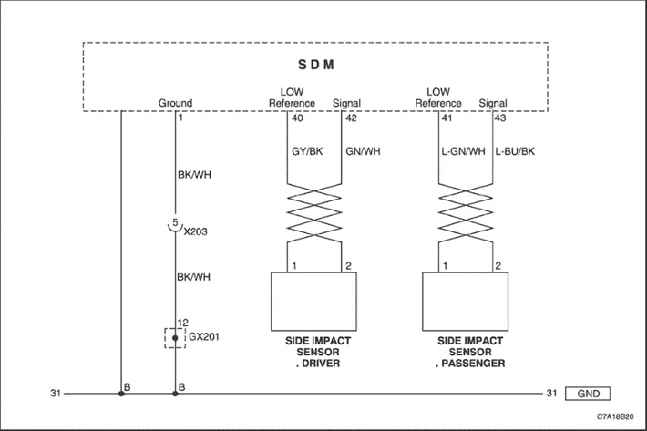
The Side Impact Sensor (SIS) uses a single-ended, 2-wire circuit. The SIS modulates the current in the interface to provide the Sensing and Diagnostic Module (SDM) with an identification code, health status, and deployment commands.
The SDM serves as a power source and ground for the SIS. When the ignition is turned on and power is initially detected from the SDM, the SIS responds by running internal diagnostics and sending an ID code to the SDM. The SDM considers the ID code to be valid if the response time is less than 5 seconds. The SIS continuously sends status messages to the SDM to determine if a fault is present in the SIS circuit. If a fault is detected, the SDM resets the SIS twice by cycling power to the SIS. If the fault persists, the SDM sets a fault code.
- Open or short to ground/battery voltage in driver SIS sensor wiring circuit for 500 ms.
- Short circuit to voltage in driver SIS sensor wiring circuit for 500 ms.
- A valid identification code message was not received within 5 seconds of power being applied to the driver SIS sensor.
- Status message not received.
- The SDM has reset the driver SIS sensor twice without detecting a valid ID message.
- The SDM has received a message from the driver SIS sensor containing an identification code that does not match the identification code stored in the SDM memory.
- The SDM has reset the driver SIS sensor twice without detecting a message with the correct identification code.
- The SDM module received a NOK message from the driver SIS sensor.
The following are conditions that may cause the malfunction:
- Short to ground or short to voltage in the driver SIS sensor circuit.
- High or low resistance in the driver SIS sensor circuit.
- The vehicle has an incorrect SIS sensor installed.
Carefully inspect the wires and connectors. Incomplete inspection of the wires and connectors may result in an erroneous diagnosis, which in turn will lead to replacement of parts with the subsequent return of the fault.
Code B0085 - "Internal Malfunction/Electronic Failure" or "Incorrect Components Installed" Side Impact Sensor (SIS): Left Front/Driver
Caution! The sensing and diagnostic module (SDM) can retain sufficient voltage to deploy the air bags and pretensioners for 1 minute after the ignition is turned off and the fuse is removed. If the air bags and pretensioners are not disconnected, do not begin servicing until one minute has passed after disconnecting power from the SDM. Failure to do so could result in personal injury.
Attention! Handle the Sensor and Diagnostic module (SDM) very carefully during maintenance. Do not hit or shake the SDM. Never connect power to the Airbag Inflator system (SIR) unless the SDM is rigidly connected to the vehicle. In order for the Airbag Inflator system (SIR) to work correctly, all the mounting bolts of the SDM sensor and diagnostic module must be carefully tightened, and the arrow on the SDM must point towards the front of the vehicle. If the SDM module is not firmly attached to the vehicle, the included module may trigger, causing the airbags to release unexpectedly and causing injury.
| Step | Operation | Values | Yes | No |
| 1 |
Has the diagnostic system check been performed?
|
-
|
Proceed to Step 2
|
Go to item "Checking the SIR diagnostic system"
|
| 2 |
Does the scan tool indicate that code B0085 is current and that code B0085 has the symptom of "Internal Electronic Failure/Defect" or "Incorrect Components Installed"?
|
-
|
Proceed to Step 3
|
See next page
|
| 3 |
Is the installed driver SIS sensor correct for the vehicle? (Please refer to the parts catalog for the correct part number for a specific vehicle)
|
-
|
Proceed to Step 4
|
-
|
| 4 |
Does the fault code re-enter?
|
-
|
Proceed to Step 5
|
The system is normal
|
| 5 |
Is the replacement complete?
|
-
|
Proceed to Step 2
|
The system is normal
|
| 6 |
Does the fault code re-enter?
|
-
|
Proceed to Step 2
|
The system is normal
|
Code B0085 - "Short to Ground or Open Circuit" or "Short to Ground" or "Short to Battery" or "Invalid Serial Data Received" or "Intermittent Malfunction" of the Side Impact Sensor (SIS): Left Front/Driver
Caution! The sensing and diagnostic module (SDM) can retain sufficient voltage to deploy the air bags and pretensioners for 1 minute after the ignition is turned off and the fuse is removed. If the air bags and pretensioners are not disconnected, do not begin servicing until one minute has passed after disconnecting power from the SDM. Failure to do so could result in personal injury.
Attention! Handle the Sensor and Diagnostic module (SDM) very carefully during maintenance. Do not hit or shake the SDM. Never connect power to the Airbag Inflator system (SIR) unless the SDM is rigidly connected to the vehicle. In order for the Airbag Inflator system (SIR) to work correctly, all the mounting bolts of the SDM sensor and diagnostic module must be carefully tightened, and the arrow on the SDM must point towards the front of the vehicle. If the SDM module is not firmly attached to the vehicle, the included module may trigger, causing the airbags to release unexpectedly and causing injury.
| Step | Operation | Values | Yes | No |
| 1 |
Has the diagnostic system check been performed?
|
-
|
Proceed to Step 2
|
Go to item "Checking the SIR diagnostic system"
|
| 2 |
Does the scan tool show that code B0085 is current?
|
-
|
Proceed to Step 10
|
Proceed to Step 3
|
| 3 |
Does the connector show any signs of damage or corrosion?
|
-
|
Proceed to Step 4
|
Proceed to Step 5
|
| 4 |
Is the repair work completed?
|
-
|
Proceed to Step 11
|
-
|
| 5 |
Does the connector show any signs of damage or corrosion?
|
-
|
Proceed to Step 6
|
Proceed to Step 7
|
| 6 |
Is the repair work completed?
|
-
|
Proceed to Step 11
|
-
|
| 7 |
Check the resistance between terminals 42, 40 of the SDM module and terminals 2, 1 of the driver SIS sensor.
Is the resistance close to 0 (zero)?
|
? 0 Ohm
|
Proceed to Step 8
|
Replace the airbag wiring
|
| 8 |
Check the resistance between pin 42 and 40 of the SDM module.
The resistance is??
|
?
|
Proceed to Step 9
|
Replace the airbag wiring
|
| 9 |
Check the resistance between terminal 42, 40 of the SDM module and ground.
Check the resistance between terminal 42, 40 of the SDM module and the battery voltage.
The resistance is??
|
?
|
Proceed to Step 10
|
Replace the airbag wiring
|
| 10 |
Replace the driver's SIS sensor.
Is the replacement complete?
|
-
|
Proceed to Step 11
|
-
|
| 11 |
Does the fault code re-enter?
|
-
|
Proceed to Step 12
|
The system is normal
|
| 12 |
Is the replacement complete?
|
-
|
Proceed to Step 13
|
-
|
| 13 |
Does the fault code re-enter?
|
-
|
Proceed to Step 2
|
The system is normal
|
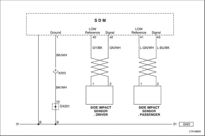
The Side Impact Sensor (SIS) uses a single-ended, 2-wire circuit. The SIS modulates the current in the interface to provide the Sensing and Diagnostic Module (SDM) with an identification code, health status, and deployment commands.
The SDM serves as a power source and ground for the SIS. When the ignition is turned on and power is initially detected from the SDM, the SIS responds by running internal diagnostics and sending an ID code to the SDM. The SDM considers the ID code to be valid if the response time is less than 5 seconds. The SIS continuously sends status messages to the SDM to determine if a fault is present in the SIS circuit. If a fault is detected, the SDM resets the SIS twice by cycling power to the SIS. If the fault persists, the SDM sets a fault code.
- Open or short to ground/battery voltage in passenger SIS sensor wiring circuit for 500 ms.
- Short circuit to voltage in passenger SIS sensor wiring circuit for 500 ms.
- A valid identification code message was not received within 5 seconds of power being applied to the passenger SIS sensor.
- Status message not received.
- The SDM has reset the passenger SIS sensor twice without detecting a valid ID message.
- The SDM has received a message from the passenger SIS sensor containing an identification code that does not match the identification code stored in the SDM memory.
- The SDM has reset the passenger SIS sensor twice without detecting a message with the correct ID code.
- The SDM module received a NOK message from the passenger SIS sensor.
The following are conditions that may cause the malfunction:
- Short to ground or short to voltage in the passenger SIS sensor circuit.
- High or low resistance in the passenger SIS sensor circuit
- The vehicle has an incorrect SIS sensor installed.
Carefully inspect the wires and connectors. Incomplete inspection of the wires and connectors may result in an erroneous diagnosis, which in turn will lead to replacement of parts with the subsequent return of the fault.
Code B0086 - "Internal Malfunction/Electronic Failure" or "Incorrect Components Installed" Side Impact Sensor (SIS): Right Front/Passenger
Caution! The sensing and diagnostic module (SDM) can retain sufficient voltage to deploy the air bags and pretensioners for 1 minute after the ignition is turned off and the fuse is removed. If the air bags and pretensioners are not disconnected, do not begin servicing until one minute has passed after disconnecting power from the SDM. Failure to do so could result in personal injury.
Attention! Handle the Sensor and Diagnostic module (SDM) very carefully during maintenance. Do not hit or shake the SDM. Never connect power to the Airbag Inflator system (SIR) unless the SDM is rigidly connected to the vehicle. In order for the Airbag Inflator system (SIR) to work correctly, all the mounting bolts of the SDM sensor and diagnostic module must be carefully tightened, and the arrow on the SDM must point towards the front of the vehicle. If the SDM module is not firmly attached to the vehicle, the included module may trigger, causing the airbags to release unexpectedly and causing injury.
| Step | Operation | Values | Yes | No |
| 1 |
Has the diagnostic system check been performed?
|
-
|
Proceed to Step 2
|
Go to item "Checking the SIR diagnostic system"
|
| 2 |
Does the scan tool indicate that code B0086 is current and that code B0086 has the symptom of "Internal Electronic Failure/Defect" or "Incorrect Components Installed"?
|
-
|
Proceed to Step 3
|
See next page
|
| 3 |
Is the installed passenger SIS sensor correct for the vehicle? (Please refer to the parts catalog for the correct part number for a specific vehicle)
|
-
|
Proceed to Step 4
|
-
|
| 4 |
Does the fault code re-enter?
|
-
|
Proceed to Step 5
|
The system is normal
|
| 5 |
Is the replacement complete?
|
-
|
Proceed to Step 2
|
The system is normal
|
| 6 |
Does the fault code re-enter?
|
-
|
Proceed to Step 2
|
The system is normal
|
Code B0086 - "Short to Ground or Open Circuit" or "Short to Ground" or "Short to Battery" or "Invalid Serial Data Received" or "Intermittent Malfunction" of the Side Impact Sensor (SIS): Right Front/Passenger
Caution! The sensing and diagnostic module (SDM) can retain sufficient voltage to deploy the air bags and pretensioners for 1 minute after the ignition is turned off and the fuse is removed. If the air bags and pretensioners are not disconnected, do not begin servicing until one minute has passed after disconnecting power from the SDM. Failure to do so could result in personal injury.
Attention! Handle the Sensor and Diagnostic module (SDM) very carefully during maintenance. Do not hit or shake the SDM. Never connect power to the Airbag Inflator system (SIR) unless the SDM is rigidly connected to the vehicle. In order for the Airbag Inflator system (SIR) to work correctly, all the mounting bolts of the SDM sensor and diagnostic module must be carefully tightened, and the arrow on the SDM must point towards the front of the vehicle. If the SDM module is not firmly attached to the vehicle, the included module may trigger, causing the airbags to release unexpectedly and causing injury.
| Step | Operation | Values | Yes | No |
| 1 |
Has the diagnostic system check been performed?
|
-
|
Proceed to Step 2
|
Go to item "Checking the SIR diagnostic system"
|
| 2 |
Does the scan tool show that code B0086 is current?
|
-
|
Proceed to Step 10
|
Proceed to Step 3
|
| 3 |
Does the connector show any signs of damage or corrosion?
|
-
|
Proceed to Step 4
|
Proceed to Step 5
|
| 4 |
Is the repair work completed?
|
-
|
Proceed to Step 11
|
-
|
| 5 |
Does the connector show any signs of damage or corrosion?
|
-
|
Proceed to Step 6
|
Proceed to Step 7
|
| 6 |
Is the repair work completed?
|
-
|
Proceed to Step 11
|
-
|
| 7 |
Check the resistance between terminals 43, 41 of the SDM module and terminals 2, 1 of the passenger SIS sensor.
Is the resistance close to 0 (zero)?
|
? 0 Ohm
|
Proceed to Step 8
|
Replace the airbag wiring
|
| 8 |
Check the resistance between pin 43 and 41 of the SDM module.
The resistance is??
|
?
|
Proceed to Step 9
|
Replace the airbag wiring
|
| 9 |
Check the resistance between terminal 43, 41 of the SDM module and ground.
Check the resistance between terminal 43, 41 of the SDM module and the battery voltage.
The resistance is??
|
?
|
Proceed to Step 10
|
Replace the airbag wiring
|
| 10 |
Replace the passenger SIS sensor.
Is the replacement complete?
|
-
|
Proceed to Step 11
|
-
|
| 11 |
Does the fault code re-enter?
|
-
|
Proceed to Step 12
|
The system is normal
|
| 12 |
Is the replacement complete?
|
-
|
Proceed to Step 13
|
-
|
| 13 |
Does the fault code re-enter?
|
-
|
Proceed to Step 2
|
The system is normal
|
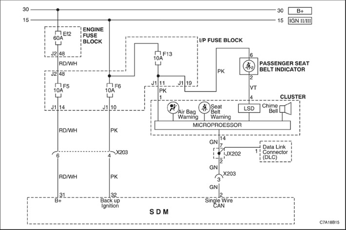
When the ignition switch is turned to the ON position, the sensing and diagnostic module (SDM) performs an initial check to detect significant problems within the SDM itself.
- The sensing and diagnostic module does not perform diagnostics. In this case, before replacing the SDM module, you must replace the module wiring harness.
Caution! The sensing and diagnostic module (SDM) can retain sufficient voltage to deploy the air bags and pretensioners for 1 minute after the ignition is turned off and the fuse is removed. If the air bags and pretensioners are not disconnected, do not begin servicing until one minute has passed after disconnecting power from the SDM. Failure to do so could result in personal injury.
Attention! Handle the Sensor and Diagnostic module (SDM) very carefully during maintenance. Do not hit or shake the SDM. Never connect power to the Airbag Inflator system (SIR) unless the SDM is rigidly connected to the vehicle. In order for the Airbag Inflator system (SIR) to work correctly, all the mounting bolts of the SDM sensor and diagnostic module must be carefully tightened, and the arrow on the SDM must point towards the front of the vehicle. If the SDM module is not firmly attached to the vehicle, the included module may trigger, causing the airbags to release unexpectedly and causing injury.
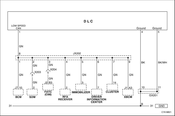
The Sensor and Diagnostic Module (SDM) of the inflatable airbag system stores the vehicle movement limiter identification code derived from the Vehicle Identification Number (VIN) and the last 4 digits of the SDM module part number. When the ignition is turned on, the SDM module compares this information with that stored in the body controller (BCM) via the GMLAN link. If the information stored in the SDM module and the BCM controller do not match, then the fault code B1001 is entered and the SDM module makes any triggers unavailable.
- The last 4 digits of the SDM part number do not match the 4 digits stored in the BCM.
- The VIN stored in the BCM does not match the actual VIN of the vehicle.
This DTC indicates that the vehicle has an incorrect SDM installed, or that the SDM and/or BCM have been replaced and the BCM has not been programmed with new information.
Caution! The sensing and diagnostic module (SDM) can retain sufficient voltage to deploy the air bags and pretensioners for 1 minute after the ignition is turned off and the fuse is removed. If the air bags and pretensioners are not disconnected, do not begin servicing until one minute has passed after disconnecting power from the SDM. Failure to do so could result in personal injury.
Attention! Handle the Sensor and Diagnostic module (SDM) very carefully during maintenance. Do not hit or shake the SDM. Never connect power to the Airbag Inflator system (SIR) unless the SDM is rigidly connected to the vehicle. In order for the Airbag Inflator system (SIR) to work correctly, all the mounting bolts of the SDM sensor and diagnostic module must be carefully tightened, and the arrow on the SDM must point towards the front of the vehicle. If the SDM module is not firmly attached to the vehicle, the included module may trigger, causing the airbags to release unexpectedly and causing injury.
| Step | Operation | Values | Yes | No |
| 1 |
Has the diagnostic system check been performed?
|
-
|
Proceed to Step 2
|
Go to item "Checking the SIR diagnostic system"
|
| 2 |
Does the scan tool show that code B1001 is current?
|
-
|
Proceed to Step 3
|
Proceed to Step 10
|
| 3 |
Using a scan tool, verify that the body control module (BCM) is programmed with the correct Vehicle Identification Number (VIN) that matches the one on the vehicle identification plate.
Is the correct VIN number programmed into the BCM?
|
-
|
Proceed to Step 5
|
Proceed to Step 4
|
| 4 |
Using a scan tool, program the correct VIN into the BCM.
Is the reprogramming procedure complete?
|
-
|
Proceed to Step 5
|
-
|
| 5 |
Using a scan tool, install the SDM part number into the BCM.
Is the reprogramming procedure complete?
|
-
|
Proceed to Step 6
|
-
|
| 6 |
Does the scan tool show this code as current?
|
-
|
Proceed to Step 7
|
Proceed to Step 10
|
| 7 |
Using a scan tool, perform a full BCM reprogramming procedure.
Is the reprogramming procedure complete?
|
-
|
Proceed to Step 8
|
-
|
| 8 |
Does the scan tool show this code as current?
|
-
|
Proceed to Step 9
|
Proceed to Step 10
|
| 9 |
Is the replacement complete?
|
-
|
Proceed to Step 10
|
-
|
| 10 |
Does the fault code re-enter?
|
-
|
Proceed to Step 2
|
The system is normal
|
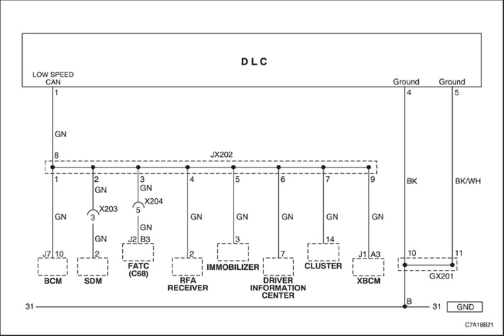
The SDM (Sensing and Diagnostic Module) of the airbag system performs continuous diagnostic tests on the system. When the ignition is turned on, the SDM will check to see if the components are installed correctly for the vehicle configuration. If the SDM detects that the system has too few or too many components, a B1019 fault code will be set and the SDM will disable any deployments. When replacing the SDM, be sure to install the correct part number for the vehicle.
- The SDM module is programmed with incorrect options that do not match the vehicle.
- An incorrect SDM module has been installed that does not match the contents of this vehicle.
This DTC indicates that the vehicle has the wrong SDM installed.
Caution! The sensing and diagnostic module (SDM) can retain sufficient voltage to deploy the air bags and pretensioners for 1 minute after the ignition is turned off and the fuse is removed. If the air bags and pretensioners are not disconnected, do not begin servicing until one minute has passed after disconnecting power from the SDM. Failure to do so could result in personal injury.
Attention! Handle the Sensor and Diagnostic module (SDM) very carefully during maintenance. Do not hit or shake the SDM. Never connect power to the Airbag Inflator system (SIR) unless the SDM is rigidly connected to the vehicle. In order for the Airbag Inflator system (SIR) to work correctly, all the mounting bolts of the SDM sensor and diagnostic module must be carefully tightened, and the arrow on the SDM must point towards the front of the vehicle. If the SDM module is not firmly attached to the vehicle, the included module may trigger, causing the airbags to release unexpectedly and causing injury.
| Step | Operation | Values | Yes | No |
| 1 |
Has the diagnostic system check been performed?
|
-
|
Proceed to Step 2
|
Go to item "Checking the SIR diagnostic system"
|
| 2 |
Does the scan tool show that code B1019 is current?
|
-
|
Proceed to Step 3
|
Proceed to Step 10
|
| 3 |
Using a scan tool, verify that the body control module (BCM) is programmed with the correct Vehicle Identification Number (VIN) that matches the one on the vehicle identification plate.
Is the correct VIN number programmed into the BCM?
|
-
|
Proceed to Step 5
|
Proceed to Step 4
|
| 4 |
Using a scan tool, program the correct VIN into the BCM.
Is the reprogramming procedure complete?
|
-
|
Proceed to Step 5
|
-
|
| 5 |
Using a scan tool, install the SDM part number into the BCM.
Is the reprogramming procedure complete?
|
-
|
Proceed to Step 6
|
-
|
| 6 |
Does the scan tool show this code as current?
|
-
|
Proceed to Step 7
|
Proceed to Step 8
|
| 7 |
Is the replacement complete?
|
-
|
Proceed to Step 8
|
-
|
| 8 |
Does the fault code re-enter?
|
-
|
Proceed to Step 2
|
The system is normal
|
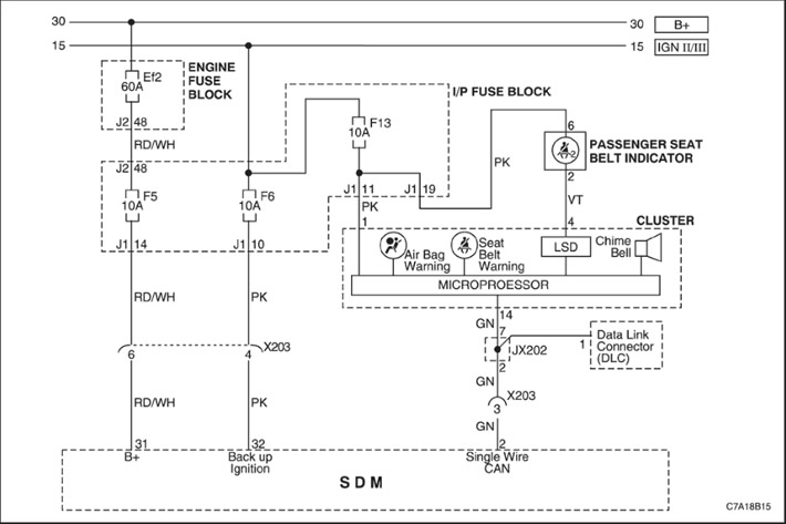
The air bag sensing and diagnostic module (SDM) monitors the ignition 1 signal from the ignition switch. When the vehicle ignition switch is turned to the RUN or CRANK position, voltage is supplied from the ignition switch to the SDM ignition 1 input terminal. If an open, short to voltage, or short to ground is detected in this SDM ignition 1 circuit, DTC B1370 sets.
- The SDM detects a short to ground or an open in the ignition 1 voltage circuit when the ignition switch is in the RUN or CRANK position.
- This condition is present for at least 10 seconds.
A history fault code may be caused by an intermittent short or open in the ignition 1 circuit.
Caution! The sensing and diagnostic module (SDM) can retain sufficient voltage to deploy the air bags and pretensioners for 1 minute after the ignition is turned off and the fuse is removed. If the air bags and pretensioners are not disconnected, do not begin servicing until one minute has passed after disconnecting power from the SDM. Failure to do so could result in personal injury.
Attention! Handle the Sensor and Diagnostic module (SDM) very carefully during maintenance. Do not hit or shake the SDM. Never connect power to the Airbag Inflator system (SIR) unless the SDM is rigidly connected to the vehicle. In order for the Airbag Inflator system (SIR) to work correctly, all the mounting bolts of the SDM sensor and diagnostic module must be carefully tightened, and the arrow on the SDM must point towards the front of the vehicle. If the SDM module is not firmly attached to the vehicle, the included module may trigger, causing the airbags to release unexpectedly and causing injury.
| Step | Operation | Values | Yes | No |
| 1 |
Has the diagnostic system check been performed?
|
-
|
Proceed to Step 2
|
Go to item "Checking the SIR diagnostic system"
|
| 2 |
Check fuse F6 in the instrument panel fuse box.
Is the fuse blown?
|
-
|
Proceed to Step 3
|
Proceed to Step 4
|
| 3 |
Replace fuse F6.
|
-
|
-
|
-
|
| 4 |
Check the voltage at fuse F6.
Is the voltage within the specified range?
|
9~16V
|
Proceed to Step 6
|
Proceed to Step 5
|
| 5 |
Repair the electrical supply and wiring to fuse F6.
|
-
|
-
|
-
|
| 6 |
Check the SDM module connector for poor contact.
Has the problem been detected and corrected?
|
-
|
Proceed to Step 10
|
Proceed to Step 7
|
| 7 |
Is the voltage within the specified range?
|
9~16V
|
Proceed to Step 9
|
Proceed to Step 8
|
| 8 |
Replace the wiring between fuse F6 and terminal 32 of the SDM module connector.
Is the replacement complete?
|
-
|
Proceed to Step 10
|
-
|
| 9 |
Is the replacement complete?
|
-
|
Proceed to Step 10
|
-
|
| 10 |
Does the fault code re-enter?
|
-
|
Proceed to Step 2
|
The system is normal
|
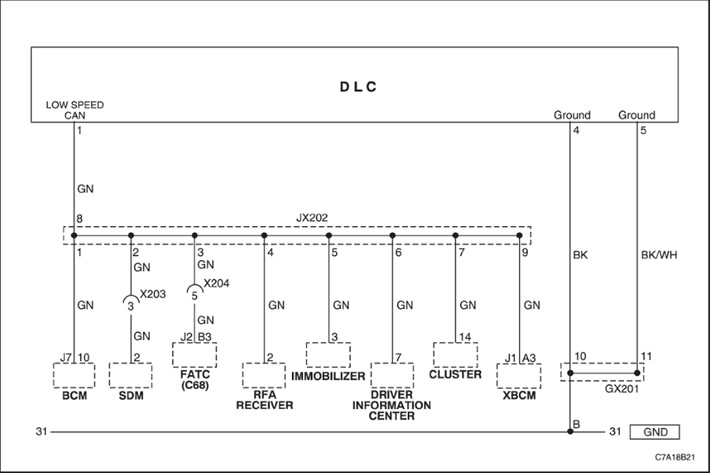
GMLAN serial communication lines are a computer area network (CAN) consisting of high-speed and low-speed serial data buses used to exchange data between controllers. Typical data rates must be high enough to provide the required response time for real-time operation.
The SDM continuously checks the trip switch position and circuit health by applying normal voltage to the trip switch circuit and checking the current.
The controller that issued the fault code attempted to establish communication on the GMLAN lines more than 7 times.
- One of the low speed GMLAN serial data lines is shorted to ground or voltage.
- An internal fault in one of the controllers causing a short to voltage or ground in the low speed GMLAN communication circuits.
Caution! The sensing and diagnostic module (SDM) can retain sufficient voltage to deploy the air bags and pretensioners for 1 minute after the ignition is turned off and the fuse is removed. If the air bags and pretensioners are not disconnected, do not begin servicing until one minute has passed after disconnecting power from the SDM. Failure to do so could result in personal injury.
Attention! Handle the Sensor and Diagnostic module (SDM) very carefully during maintenance. Do not hit or shake the SDM. Never connect power to the Airbag Inflator system (SIR) unless the SDM is rigidly connected to the vehicle. In order for the Airbag Inflator system (SIR) to work correctly, all the mounting bolts of the SDM sensor and diagnostic module must be carefully tightened, and the arrow on the SDM must point towards the front of the vehicle. If the SDM module is not firmly attached to the vehicle, the included module may trigger, causing the airbags to release unexpectedly and causing injury.
| Step | Operation | Values | Yes | No |
| 1 |
Has the diagnostic system check been performed?
|
-
|
Proceed to Step 2
|
Go to item "Checking the SIR diagnostic system"
|
| 2 |
Does the scan tool communicate with any controller connected to the low speed GMLAN data line?
|
-
|
Proceed to Step 3
|
Proceed to Step 5
|
| 3 |
Are any of the U0140 and U0155 fault codes recorded?
|
-
|
Proceed to the appropriate trouble code diagnostic section
|
Proceed to Step 4
|
| 4 |
Check for an open or short to ground or voltage in the low speed GMLAN serial data circuits at each connected controller.
Has the problem been detected and corrected?
|
-
|
Proceed to Step 16
|
Proceed to Step 5
|
| 5 |
Has the problem been detected and corrected?
|
-
|
Proceed to Step 13
|
Proceed to Step 6
|
| 6 |
Has the problem been detected and corrected?
|
-
|
Go to item "Checking the SIR diagnostic system"
|
Proceed to Step 7
|
| 7 |
Does the scan tool communicate with the BCM?
|
-
|
Proceed to Step 11
|
Proceed to Step 8
|
| 8 |
Does the scan tool communicate with the BCM?
|
-
|
Proceed to Step 9
|
Proceed to Step 10
|
| 9 |
Check for a short to ground or short to voltage in the low speed GMLAN serial data circuits between the last two disconnected modules.
Has the problem been detected and corrected?
|
-
|
Proceed to Step 9
|
Proceed to Step 10
|
| 10 |
Is the BCM the last device still connected to the low speed GMLAN serial data line?
|
-
|
Proceed to Step 11
|
Proceed to Step 8
|
| 11 |
Has the problem been detected and corrected?
|
-
|
Proceed to Step 14
|
Proceed to Step 12
|
| 12 |
Check for poor connections in the low speed GMLAN serial data circuit at the last module disconnected.
Has the problem been detected and corrected?
|
-
|
Proceed to Step 14
|
Proceed to Step 13
|
| 13 |
Is the replacement complete?
|
-
|
Proceed to Step 14
|
-
|
| 14 |
Are there any fault codes stored that start with "U" and have a status of Current?
|
-
|
Go to item "Checking the SIR diagnostic system"
|
Proceed to Step 15
|
| 15 |
Are there any fault codes stored that do not begin with "U"?
|
-
|
Go to item "Checking the SIR diagnostic system"
|
Proceed to Step 16
|
| 16 |
Have all fault codes been diagnosed?
|
-
|
Proceed to Step 17
|
Proceed to Step 14
|
| 17 |
Use a scan tool to clear any existing fault codes.
Is the action completed?
|
-
|
The system is normal
|
-
|
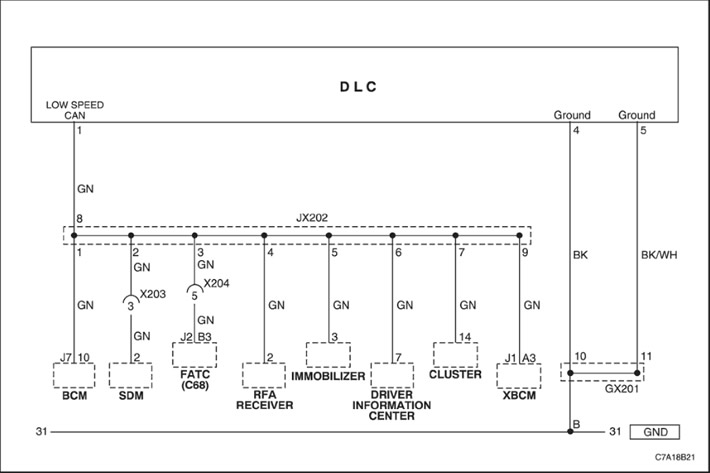
During normal vehicle operation, the controllers connected to the GMLAN serial communication line monitor the transmission of data. Operational information and commands are exchanged between the controllers. The controllers have stored information about what messages should be exchanged over the serial communication lines in each virtual network. These messages are also monitored, and certain regular messages are used by the receiving controller to determine the availability of the transmitting controller. The verification delay time is 250 milliseconds. Each message contains the identification number of the transmitting controller. If a message indicating the availability of the transmitting controller is not received, the receiving controller sets the U01xx fault code, where "xx" is the 2-digit identification number of the transmitting controller.
For a module that has lost GMLAN serial communication or power is removed during the current ignition cycle, a Communication Lost DTC will be set by other modules that require data from the failed module. Modules that do not have a communication loss will set a DTC indicating the module with the communication loss.
- The voltage supplied to the controllers is within the normal operating voltage range.
- The vehicle's power supply mode necessitates a serial communication session.
- DTC U0073 does not have a current status.
- Communication failure between the SDM module and the BCM controller.
- This fault code may be set due to a poor connection in the failed controller.
- This fault code may be set due to a power failure in the controller.
Caution! The sensing and diagnostic module (SDM) can retain sufficient voltage to deploy the air bags and pretensioners for 1 minute after the ignition is turned off and the fuse is removed. If the air bags and pretensioners are not disconnected, do not begin servicing until one minute has passed after disconnecting power from the SDM. Failure to do so could result in personal injury.
Attention! Handle the Sensor and Diagnostic module (SDM) very carefully during maintenance. Do not hit or shake the SDM. Never connect power to the Airbag Inflator system (SIR) unless the SDM is rigidly connected to the vehicle. In order for the Airbag Inflator system (SIR) to work correctly, all the mounting bolts of the SDM sensor and diagnostic module must be carefully tightened, and the arrow on the SDM must point towards the front of the vehicle. If the SDM module is not firmly attached to the vehicle, the included module may trigger, causing the airbags to release unexpectedly and causing injury.
| Step | Operation | Values | Yes | No |
| 1 |
Has the diagnostic system check been performed?
|
-
|
Proceed to Step 2
|
Go to item "Checking the SIR diagnostic system"
|
| 2 |
Check for an open or short to ground or voltage in the low speed GMLAN serial data circuit at the BCM.
Has the problem been detected and corrected?
|
-
|
Proceed to Step 6
|
Proceed to Step 3
|
| 3 |
Check the BCM controller connector for poor connections.
Has the problem been detected and corrected?
|
-
|
Proceed to Step 6
|
Proceed to Step 4
|
| 4 |
Has the problem been detected and corrected?
|
-
|
Proceed to Step 6
|
Proceed to Step 5
|
| 5 |
Is the replacement complete?
|
-
|
Proceed to Step 6
|
-
|
| 6 |
Are any DTCs displayed on the scan tool that do not begin with "U"?
|
-
|
Proceed to the appropriate trouble code diagnostic section
|
Proceed to Step 7
|
| 7 |
Select the function to read fault codes for the SDM controller.
Are any DTCs displayed on the scan tool that do not begin with "U"?
|
-
|
Proceed to the appropriate trouble code diagnostic section
|
Proceed to Step 8
|
| 8 |
Is the action completed?
|
-
|
The system is normal
|
-
|
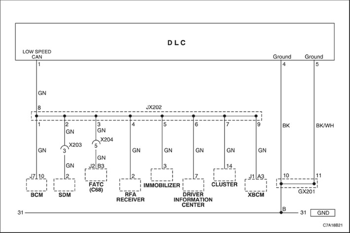
During normal vehicle operation, the controllers connected to the GMLAN serial communication line monitor the transmission of data. Operational information and commands are exchanged between the controllers. The controllers have stored information about what messages should be exchanged over the serial communication lines in each virtual network. These messages are also monitored, and certain regular messages are used by the receiving controller to determine the availability of the transmitting controller. The verification delay time is 250 milliseconds. Each message contains the identification number of the transmitting controller. If a message indicating the availability of the transmitting controller is not received, the receiving controller sets the U01xx fault code, where "xx" is the 2-digit identification number of the transmitting controller.
For a module that has lost GMLAN serial communication or power is removed during the current ignition cycle, a Communication Lost DTC will be set by other modules that require data from the failed module. Modules that do not have a communication loss will set a DTC indicating the module with the communication loss.
- The voltage supplied to the controllers is within the normal operating voltage range.
- The vehicle's power supply mode necessitates a serial communication session.
- DTC U0073 does not have a current status.
- Communication failure between the SDM module and the instrument cluster (IPC).
- This fault code may be set due to a poor connection in the failed controller.
- This fault code may be set due to a power failure in the controller.
Caution! The sensing and diagnostic module (SDM) can retain sufficient voltage to deploy the air bags and pretensioners for 1 minute after the ignition is turned off and the fuse is removed. If the air bags and pretensioners are not disconnected, do not begin servicing until one minute has passed after disconnecting power from the SDM. Failure to do so could result in personal injury.
Attention! Handle the Sensor and Diagnostic module (SDM) very carefully during maintenance. Do not hit or shake the SDM. Never connect power to the Airbag Inflator system (SIR) unless the SDM is rigidly connected to the vehicle. In order for the Airbag Inflator system (SIR) to work correctly, all the mounting bolts of the SDM sensor and diagnostic module must be carefully tightened, and the arrow on the SDM must point towards the front of the vehicle. If the SDM module is not firmly attached to the vehicle, the included module may trigger, causing the airbags to release unexpectedly and causing injury.
| Step | Operation | Values | Yes | No |
| 1 |
Has the diagnostic system check been performed?
|
-
|
Proceed to Step 2
|
Go to item "Checking the SIR diagnostic system"
|
| 2 |
Check for an open or short to ground or voltage in the low speed GMLAN serial data circuit at the instrument cluster.
Has the problem been detected and corrected?
|
-
|
Proceed to Step 6
|
Proceed to Step 3
|
| 3 |
Check the instrument cluster connector for poor contact.
Has the problem been detected and corrected?
|
-
|
Proceed to Step 6
|
Proceed to Step 4
|
| 4 |
Has the problem been detected and corrected?
|
-
|
Proceed to Step 6
|
Proceed to Step 5
|
| 5 |
Is the replacement complete?
|
-
|
Proceed to Step 6
|
-
|
| 6 |
Are any DTCs displayed on the scan tool that do not begin with "U"?
|
-
|
Proceed to the appropriate trouble code diagnostic section
|
Proceed to Step 7
|
| 7 |
Select the function to read fault codes for the SDM controller.
Are any DTCs displayed on the scan tool that do not begin with "U"?
|
-
|
Proceed to the appropriate trouble code diagnostic section
|
Proceed to Step 8
|
| 8 |
Is the action completed?
|
-
|
The system is normal
|
-
|
(The original article can be found on the resource: ChevyMan)