Cylinder head
This cylinder head is of the SOHC type (with single overhead camshaft) and has only one camshaft that opens 4 valves per cylinder using roller-type tappets and valve bridges. It is similar to a DOHC cylinder head (with double overhead camshaft).
The camshaft gear is installed in front of the camshaft, and the vacuum pump is attached to the rear of the camshaft. Since the valve lifter is a hydraulic type, there is no need to adjust the valve clearance.
The cylinder head is made from cast aluminum alloy for increased strength combined with light weight.
The cylinder head's plate-type combustion chamber is designed to improve swirl and compression efficiency at the end of the compression stroke, thereby maximizing diesel fuel combustion efficiency.
Cylinder block
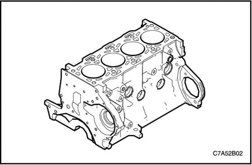
The engine block, as the largest part of the engine components, is made of cast iron. The inside of the engine block contains channels for engine oil and coolant for lubrication and cooling. On the top side of the engine block is the cylinder head, which contains the combustion chamber. The engine block also has a support plate on the bottom to support the crankshaft and reduce engine vibration.
On the inner surface of the engine cylinder block there are surfaces of boring holes in which reciprocating pistons are arranged, and 4 nozzles for jet lubrication on each surface of the boring hole.
Valve mechanism
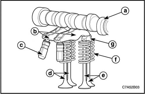
The engine uses a valve tappet and hydraulic valve clearance adjustment to drive the valve.
In the middle of the valve follower there is a roller which continuously transmits the movement of the cam to the valve bridge in accordance with the cam profile.
|
Designation
|
Name
|
PURPOSE
|
|
a
|
Camshaft
|
Drives the valve system
|
|
b
|
Valve tappet finger
|
Transmits rotation to the valve bridge
|
|
c
|
Hydraulic valve clearance compensator
|
Rotates and compensates by activating and deactivating movement
|
|
d
|
Inlet valve
|
Creates a fresh gas flow
|
|
e
|
Exhaust valve
|
Creates a flow of exhaust gases
|
|
f
|
Valve spring
|
Holds the valve in the closed position
|
|
G
|
Valve bridge
|
Activates the movement of two valves
|
Crankshaft
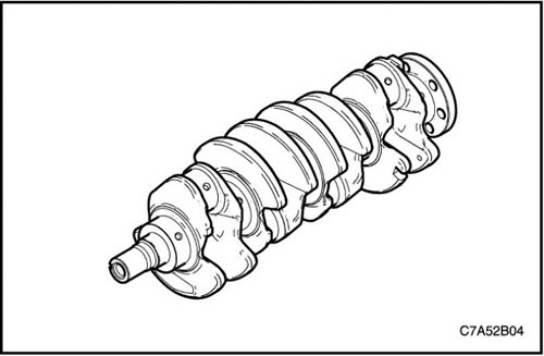
The crankshaft is made of a forged structure, which provides a higher tensile strength than cast iron. It is located between the engine block and the support plate on 5 main journals with main bearings, which have an oil gap for lubrication. The 3rd of the 5 main bearings is a thrust bearing, due to which the crankshaft has the correct axial clearance.
The crankshaft is assembled from 4 connecting rod journals with metal bearing liners, the covers of which are transversely fastened with bolts to enhance structural rigidity.
On the front side of the crankshaft is the crankshaft gear which drives the oil pump and the crankshaft balancer. On the back side of the crankshaft is a wheel with a "target" to send a signal to the CPS (crankshaft position sensor).
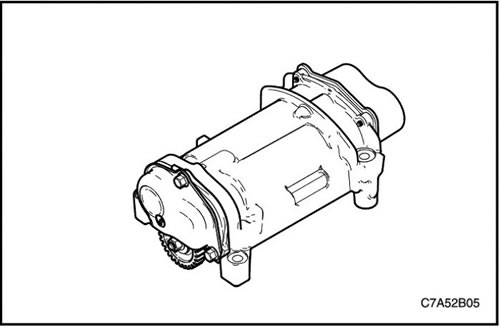
Crankshaft balancer assembly
The crankshaft gear drives 2 counter-rotating balance shafts. The balancer thus balances the vibration from the crank mechanism. It is located between the support plate and the oil pan with engine oil.
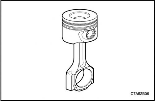
Piston, connecting rod assembly
The pistons are cast from aluminum with a combustion chamber in the bottom. They have 2 compression rings and 1 oil scraper ring assembled with a spring. Between the piston pin hole and the connecting rod pin hole there is a fully floating piston pin, which is secured with a clamp at both ends.
The connecting rod and big end cap with bearings are installed in place and secured with bolts.
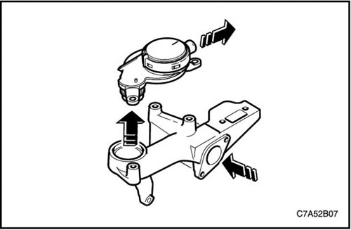
Positive Crankcase Ventilation (PCV) Valve
The PCV valve transfers crankcase gases to the turbocharger intake port of the intake system. Depending on the engine condition, driving conditions and turbocharger pressure, the amount of crankcase gases changes. Thus, the PCV valve regulates the amount of crankcase gases.
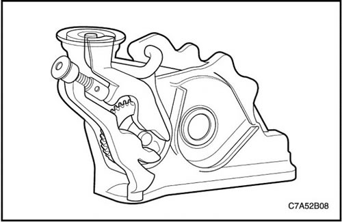
Oil pump
The oil pump draws engine oil from the oil pan and delivers it under pressure to various parts of the engine. An oil filter is installed before the inlet to the oil pump to remove contaminants that could clog or damage the oil pump or other engine components. As the crankshaft rotates, the driven gear of the oil pump rotates. This causes the gap between the gears to constantly narrow and open, sucking oil from the oil pan when the gap opens and pumping oil into the engine when it narrows.
At high engine speeds, the oil pump delivers much more oil than is needed to lubricate the engine.
The oil pressure regulator prevents excess oil from entering the engine's lubrication passages. When the oil supply is normal, the coil spring and valve hold the bypass closed, directing all the oil into the engine. As the volume of oil being pumped increases, the pressure increases to a level sufficient to overcome the spring force.
This opens the oil pressure regulating valve, allowing oil to flow through the valve and drain back into the oil pan.
Gas distribution system
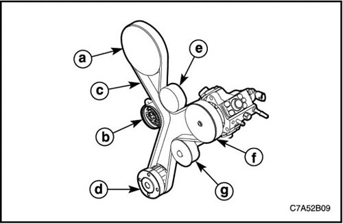
The crankshaft pulley, together with the crankshaft, drives the camshaft sprocket, water pump pulley and high-pressure pump sprocket via the timing belt. The timing belt is also tensioned by a double-eccentric automatic tensioner.
The timing belt idler pulley, which adopts double-row bearing type to withstand heavy loads, increases the wrap angle between the camshaft sprocket and the high-pressure pump sprocket to increase the power output.
|
Designation
|
Name
|
PURPOSE
|
|
a
|
Camshaft sprocket
|
Drives the camshaft.
|
|
b
|
Gas distribution mechanism drive belt tensioner
|
Adjusts the tension of the timing belt.
|
|
c
|
Gas distribution mechanism drive belt
|
Transmits power to the pulley and sprocket.
|
|
d
|
Crankshaft sprocket
|
Transmits power from the crankshaft.
|
|
e
|
Timing Belt Drive Idle Pulley
|
Increases the angles of coverage.
|
|
f
|
High pressure pump sprocket
|
Drives the high pressure pump.
|
|
G
|
Water pump pulley
|
Drives the water pump.
|
Intake manifold
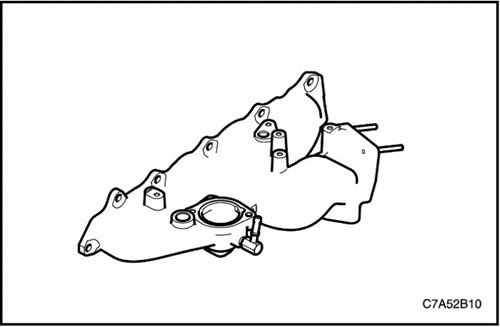
The intake manifold is the passageway for air flow into the cylinder combustion chamber through the throttle body and affects engine torque, power, noise, vehicle handling, emissions, fuel economy and performance.
It is cast from aluminum alloy for increased strength combined with light weight and is integral with the coolant passage.
Exhaust manifold
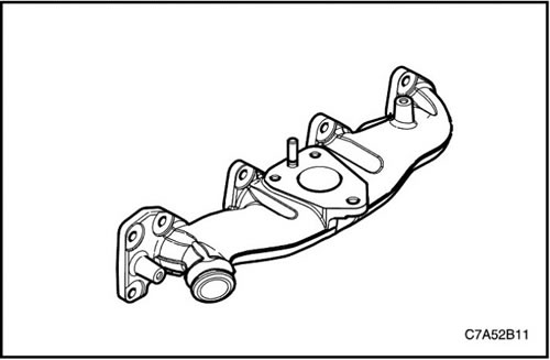
The exhaust manifold is placed on the cylinder head and sends exhaust gases from the combustion chamber to the turbocharger. It is designed to withstand high pressure and high temperature and is made from HiSiMo material.
Charge air cooler
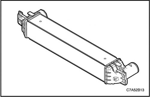
A turbocharger is a device that supplies hot and compressed air, i.e. from a turbine, by sucking in exhaust gases or ram air, into an engine to increase power.
The rapidly compressed air from this turbocharger expands at high temperature and causes a reduction in the efficiency of the charge into the cylinder as the oxygen concentration decreases.
However, the efficiency of charging into the cylinder increases as the compressed hot air cools and the air density increases as it passes through the charge air cooler.
It also helps improve fuel economy and reduce CO₂ emissions.
A charge air cooler, mounted on top of the radiator at the front of the vehicle, cools the compressed hot air by directing air flow through the radiator grille.
Vacuum pump
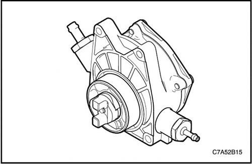
The vacuum pump provides vacuum for the brake booster and the exhaust gas recirculation (EGR) controller on a diesel engine and is mounted on the top left side of the engine to mate with the camshaft and is driven from the camshaft on a Euro 4 diesel engine.
Suspension
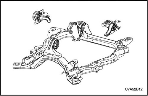
The engine suspension system is used to mount the power plant on the body and support the power plant in its designed fixed position. The suspensions are designed to reduce dynamic loads, both internally generated by the power plant and external road impacts by isolating the vehicle from the power plant, regulating the movement of the power plant and counteracting the forces and torques of the power plant.
The engine suspension system consists of four suspensions: Left and right load-bearing support suspensions and front and rear anti-torque suspensions.
The right (engine) mount is a normal mount, while the left (gearboxes) is a hydraulic suspension. Both front and rear suspensions are of standard type.