
Contents: Disassembly procedure ↧ Checking the cylinder head ↧ Checking the valves ↧ Cleaning procedure ↧ Assembly procedure ↧
Necessary equipment
09916-14510 Valve Spring Compressor
EN-48247 Valve Spring Compression Pressure Adapter
EN-48252 Camshaft Oil Seal Installer
Disassembly procedure
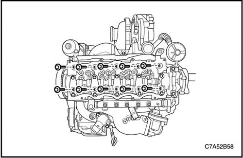
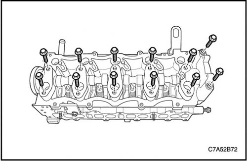
1. Remove the cylinder head. Follow step "Cylinder head and gasket" in this section.
2. Remove the intake manifold. See item "Intake manifold" in this section.
3. Remove the exhaust manifold. Follow step "Exhaust manifold" in this section.
4. Remove the vacuum pump. See Section 1F1, Engine Controls - 2.0 Diesel.

5. Remove the camshaft sprocket.
6. Remove the camshaft cover.
7. Remove the camshaft.
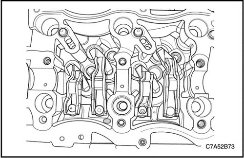
8. Remove the intake/exhaust roller tappets
9. Remove the intake/exhaust valve bridge.
10. Remove the intake/exhaust valve clearance compensator.
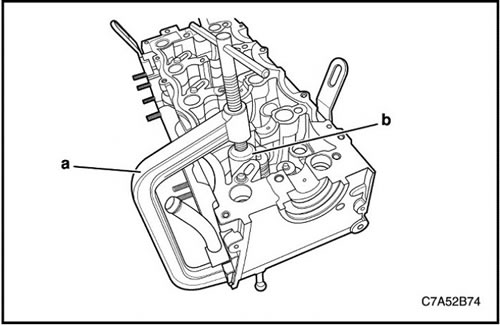
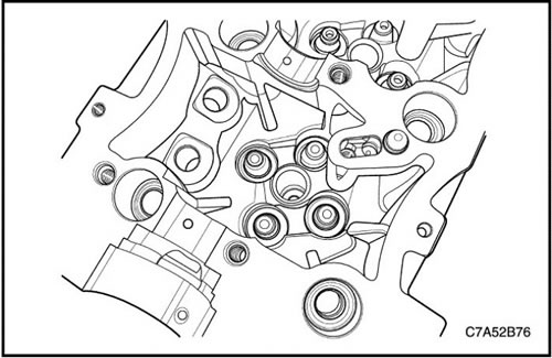
11. Install valve spring compressor 09916-14510 (a) together with valve spring compression pressure adapter EN-48247 (b) to the cylinder head.
12. To compress the valve spring, turn the handle of the valve spring compressor 09916-14510.
13. Remove the valve key.
14. Remove the valve spring retainer.
15. Remove the valve spring.
16. Remove the valves.
17. Remove the valve stem seal.
Checking the cylinder head
1. Clean the sealing surfaces.
2. Check the cylinder head for the following conditions.
- Cracks, damage or chipping of the surface in the combustion chambers;
- Foreign particles in lubrication channels; Thoroughly clean the canals from foreign particles;
- Coolant leaks or damage to the sealing surface of the cylinder head face;
- Damage to any gasket surfaces;
- Damage to the threaded holes of any of the bolts;
- Burnt or eroded areas in the combustion chamber;
- Cracks in exhaust ports and combustion chambers;
- External cracks in water channels;
- Restrictions in the intake or exhaust ports;
- Restrictions in cooling system channels;
- Rusty, damaged or leaking plugs.
3. If cracks or damage are found on the cylinder head, it must be replaced. It is not recommended to carry out welding work on the cylinder head or repair damage.
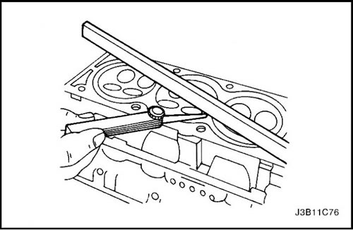
4. Measure the gap between the straightedge and the face of the cylinder head at four points along the straightedge using a gap gauge.
5. Check the sealing surfaces for deformation and distortion. The cylinder head sealing surfaces must be aligned within 0.05 mm (0.002 inches).

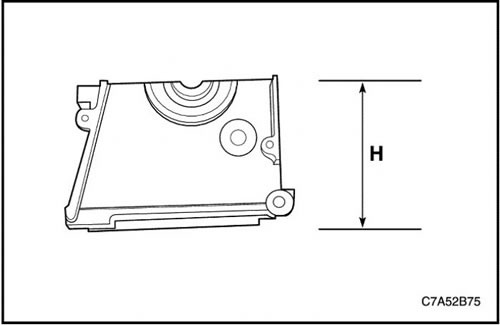
6. Measure the height of the cylinder head from sealing surface to sealing surface. The height of the cylinder head should be between 129.9 and 130.1 mm (from 5.1142 to 5.1220 inches). If the cylinder head height is less than the permissible specifications, replace the cylinder head.
Checking the valves
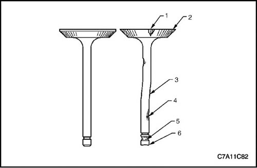
1. Check for valve damage from head to stop as follows.
-
2. Is there any surface chipping in the valve seat area (1)
3. Is the valve edge (2) the correct shape?
4. Is there a bend in the valve stem (3)
5. Is there any surface chipping or excessive wear in the piston rod (4)
6. Are the valve key grooves worn out (5)?
7. Is the valve stop (6) worn out?
8. Replace the valve if any of these signs occur.
9. Check the valve springs. If the end of the valve spring is not parallel, replace the valve spring.
10. Check the valve seat for wear or chipping. Replace if necessary.
Cleaning procedure
1. Clean the cylinder head.
2. Clean the valve guides.
3. Clean all threaded holes.
4. Clean the valves from soot, oil and carbon deposits.
Assembly procedure
1. Lubricate the valve stems with engine oil.
2. Carefully return the valves to their original positions.
3. Install the valve stem seal.

4. Install the valve spring.
5. Install the valve spring support cup.
6. Install the valve.
7. Install the valve spring retainer.
8. Compress the valve springs using the 09916-14510 Valve Spring Compressor (a) and EN-48247 Valve Spring Compression Pressure Adapter (b).
9. Install the valve key.
10. Remove valve spring compressor 09916-14510 (a) and valve spring compression pressure adapter EN-48247 (b).

11. Install valve clearance adjusters.
12. Install the valve bridges.
13. Install the roller valve tappets.
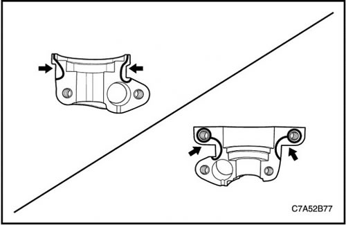
14. Apply sealant (LOCTITE 573) on the sealing surface of the front/rear camshaft cover.

15. Install the camshaft.
16. Install the camshaft cover.
Tighten
Tighten the camshaft cover bolts to 28 N·m (20.7 ft·lbs).
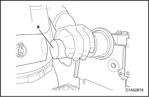
17. Install the front camshaft oil seal ring using the EN-48252 camshaft oil seal installer (a).
Note: If the front camshaft oil seal is damaged, it must be replaced with a new one. When installing the front camshaft oil seal to the oil pump, make sure that the groove of the oil seal faces the contact direction on the oil pump housing.
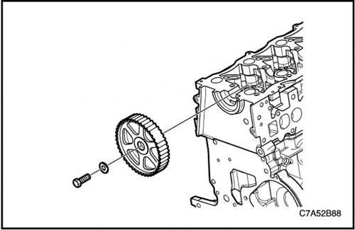
18. Install the camshaft sprocket.
Tighten
Tighten the camshaft sprocket bolt to 133 N·m (98.1 ft·lbs).
