


Contents: Gearbox Description ↧ Electronic components ↧ Gearbox controller ↧ Gearbox range switch ↧ Solenoid valve for switching No.1,… ↧ Solenoid valve for regulating… ↧ Torque Converter Clutch Lock-Up… ↧ Shift Pressure Control Solenoid… ↧ Automatic transmission fluid… ↧ Gearbox primary shaft speed sensor ↧ Gearbox secondary shaft speed sensor ↧ Hydraulic control system ↧ Automatic transmission (AT) ↧ Purpose of components ↧ Operation of friction clutches and… ↧ D - 1st gear ↧ D - 2nd gear ↧ D - 3rd gear ↧ D - 4th gear ↧ D-5th gear ↧ Reverse ↧ Control functions of the gearbox… ↧ Switch control and lock control ↧ Manual gear shift control… ↧ Lock Off Control ↧ Upshift/Downshift Learning Management ↧ ND Switching Control ↧ ND Learning Management ↧ NR Switching Control ↧ NR Learning Management ↧ Torque reduction control ↧ Adaptive learning procedure of the… ↧
Gearbox Description
New automatic transmission (AISIN 55-51LE) is a five-speed automatic transmission with electronic control.
The main elements of the gearbox are the torque converter, planetary gear, hydraulic control system and electronic control system.
Electronic components
Gearbox controller
The main function of the automatic transmission controller is to determine the moments of gear shifting and the engagement of the torque converter lockup clutch. It is located under the instrument panel on the driver's side.
The gear shifting of the automatic transmission is controlled by an electronic system. The controller processes the signals received by it. Based on the information received, the gearbox controller controls the hydraulic system.
The electronic control system consists of the following elements:
- Automatic transmission controller
- Shift Solenoid Valves (SS1, SS2, SS3, SS4 and SS5)
- Gearbox primary shaft speed sensor
- Gearbox secondary shaft speed sensor
- Automatic transmission fluid temperature sensor
- Gearbox range switch
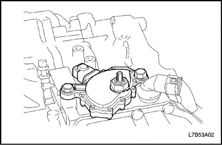
Gearbox range switch
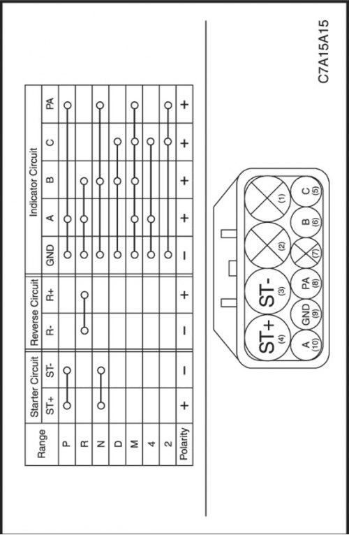
The range switch transmits information to the starter and automatic transmission controller depending on the position of the gear shift lever.
- The engine can only be started if the range selector is in the "P" or "N" position. (Protection against engine starting with the gear engaged.)
- When reversing, the automatic transmission range switch gives a command to turn on the reversing lights.
- The information received is used to control gear shifting.
The automatic transmission range switch transmits signals to the starter and reverse circuit, bypassing the automatic transmission controller.
Solenoid valve for switching No.1, 2, 3, 4, 5 (SS1, SS2, SS3, SS4, SS5)
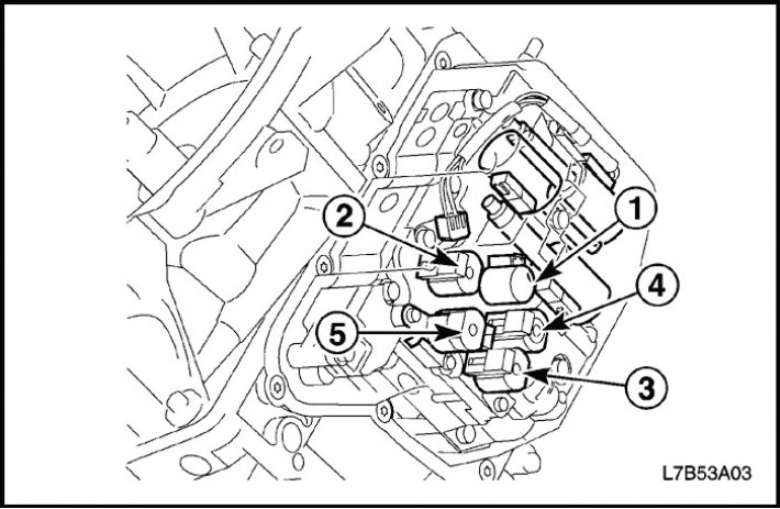
5 electromagnetic shift valves are installed in the valve mechanism housing. The electromagnetic valves perform switching on and off according to the control signal from the gearbox controller. Combinations of the 5 electromagnetic shift valves, SS1, SS2, SS3, SS4 and SS5, change the gear ranges.
Solenoid valve for regulating pressure in hydraulic lines (SLT)
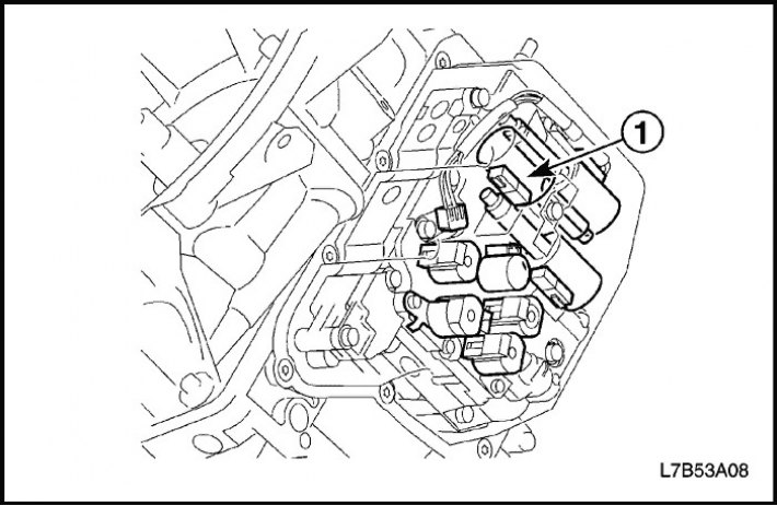
The solenoid valve for regulating hydraulic line pressure (SLT) regulates the line pressure before the throttle valve using a control signal from the TCM and the pressure in the hydraulic lines of the clutches and brakes to reduce shock during gear shifts.
Torque Converter Clutch Lock-Up Solenoid Valve (SLU)
The torque converter clutch lock-up (SLU) control solenoid valve regulates the SLU line pressure using the control signal from the TCM and the clutch lock-up hydraulic pressure to reduce shift shock.
"Direct control"
1st gear, engine braking - 1st gear and reverse brake (B3)
2nd gear - 2nd gear brake (B2)
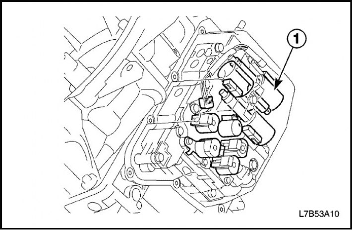
Shift Pressure Control Solenoid Valve (SLS)
The shift pressure control (SLS) solenoid valve regulates the SLS line pressure using a control signal from the TCM.
"Direct control"
2nd, 3rd, 4th gear - 2nd gear inertia brake (B1)
5th gear, reverse gear - direct drive clutch (C2)
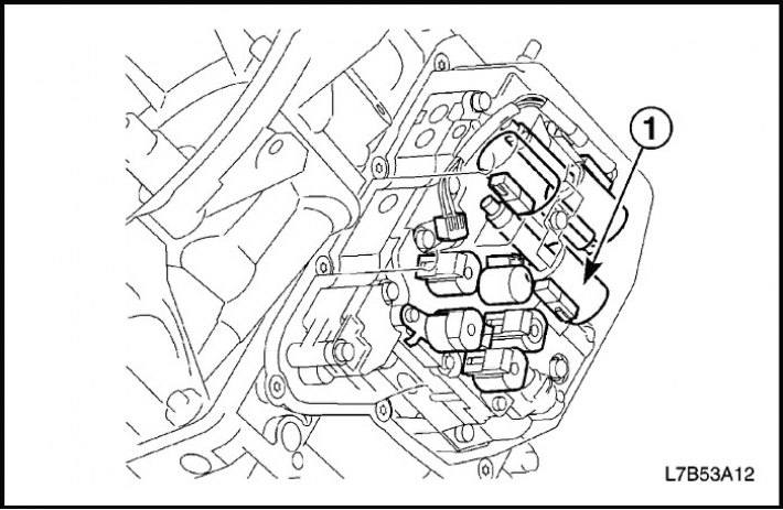
Automatic transmission fluid temperature sensor
The transmission fluid temperature sensor is located in the valve block.
The automatic transmission fluid temperature sensor transmits data on the temperature of the automatic transmission fluid to the gearbox controller.
The controller uses the received data to calculate the gear shift moments and engagement of the torque converter lock-up clutch.
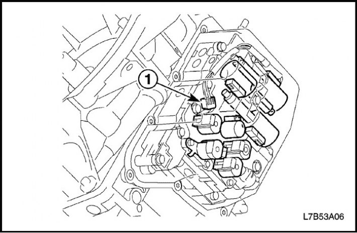
Gearbox primary shaft speed sensor
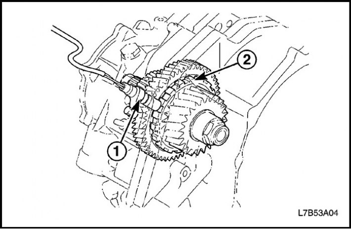
The primary shaft speed sensor of the gearbox with the final drive assembly (1), installed in the upper part of the gearbox with the final drive assembly, determines the rotation speed of the primary shaft based on the number of revolutions of the drum (2) of the direct drive clutch.
The sensor transmits a signal about the shaft speed to the gearbox controller.
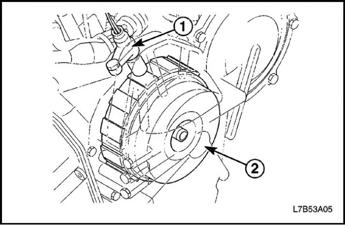
Gearbox secondary shaft speed sensor
The gearbox secondary shaft speed sensor (1), mounted on the top of the gearbox, detects the vehicle speed based on the number of revolutions of the parking gear pinion (2).
Hydraulic control system
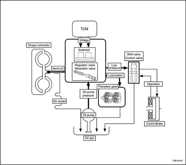
Depending on the pressure generated by the oil pump, the gearbox controller issues commands to turn on/off the electromagnetic valves of the hydraulic system, which controls the operation of the torque converter, planetary gear, clutches and brakes in accordance with the vehicle's driving mode.
Automatic transmission (AT)
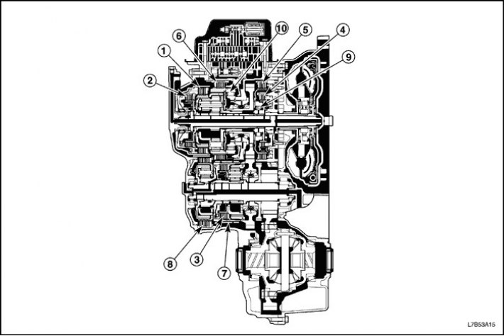
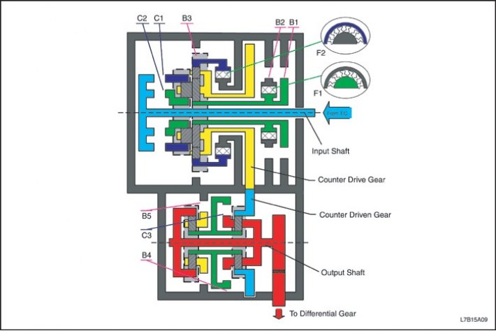
Purpose of components
|
Clutch and brake
|
Purpose
|
|
|
C1
|
Forward clutch (1)
|
Providing connection between the primary shaft and the epicyclic gear of the rear planetary gear set.
|
|
C2
|
Direct Drive Clutch (2)
|
Providing connection between the primary shaft and the rear planetary gear sun wheel.
|
|
C3
|
Downshift clutch (3)
|
Providing connection between the downshift sun wheel and the downshift front planetary gear carrier.
|
|
B1
|
2nd gear inertia brake (4)
|
Providing locking of the front planetary gear sun wheel.
|
|
B2
|
2nd gear brake (5)
|
Ensuring the counter-clockwise rotation lock of the front planetary gear set sun wheel.
|
|
B3
|
1st gear and reverse brake (6)
|
Providing locking of the epicyclic gear of the rear planetary row.
|
|
B4
|
Downshift brake (7)
|
Providing blocking of the downshift sun wheel.
|
|
B5
|
Brake B5 (8)
|
Providing locking of the rear planetary gear set driver.
|
|
F1
|
Overrunning clutch No.1 (9)
|
Ensuring the counter-clockwise rotation lock of the front planetary gear sun wheel when the B2 brake is engaged.
|
|
F2
|
Overrunning clutch No.2 (10)
|
Ensuring the counter-clockwise rotation lock of the front planetary gear epicyclic gear.
|
Operation of friction clutches and brakes
|
Position
|
Solenoid
|
Coupling
|
Brake
|
Overrunning clutch
|
|||||||||||||
|
S1
|
S2
|
S3
|
S4
|
S5
|
C1
|
C2
|
C3
|
B1
|
B2
|
B3
|
B4
|
B5
|
F1
|
F2
|
|||
|
P
|
Off.
|
Off.
|
Off.
|
Off.
|
Off.
|
Off.
|
Off.
|
Off.
|
Off.
|
Off.
|
Off.
|
Off.
|
On.
|
Off.
|
Off.
|
||
|
R
|
V≤7
|
Off.
|
Off.
|
On.
|
Off.
|
On.
|
Off.
|
On.
|
Off.
|
Off.
|
Off.
|
On.
|
Off.
|
On.
|
Off.
|
Off.
|
|
|
V>7
|
On.
|
Off.
|
Off.
|
Off.
|
Off.
|
Off.
|
Off.
|
Off.
|
Off.
|
Off.
|
Off.
|
Off.
|
On.
|
Off.
|
Off.
|
||
|
N
|
Off.
|
Off.
|
Off.
|
Off.
|
Off.
|
Off.
|
Off.
|
Off.
|
Off.
|
Off.
|
Off.
|
Off.
|
On.
|
Off.
|
Off.
|
||
|
D, M
|
D
|
1st
|
On.
|
On.
|
On.
|
Off.
|
Off.
|
On.
|
Off.
|
Off.
|
Off.
|
Off.
|
Off.
|
Off.
|
On.
|
Off.
|
On.
|
|
M
|
1st
|
On.
|
On.
|
On.
|
Off.
|
On.
|
On.
|
Off.
|
Off.
|
Off.
|
Off.
|
On.
|
Off.
|
On.
|
Off.
|
On.
|
|
|
2nd
|
Off.
|
Off.
|
On.
|
Off.
|
Off.
|
On.
|
Off.
|
Off.
|
On.
|
On.
|
Off.
|
Off.
|
On.
|
On.
|
Off.
|
||
|
3rd
|
Off.
|
Off.
|
On.
|
On.
|
Off.
|
On.
|
Off.
|
Off.
|
On.
|
On.
|
Off.
|
On.
|
Off.
|
On.
|
Off.
|
||
|
4th
|
Off.
|
Off.
|
Off.
|
On.
|
Off.
|
On.
|
Off.
|
On.
|
On.
|
On.
|
Off.
|
Off.
|
Off.
|
On.
|
Off.
|
||
|
5th
|
Off.
|
On.
|
Off.
|
On.
|
Off.
|
On.
|
On.
|
On.
|
Off.
|
On.
|
Off.
|
Off.
|
Off.
|
Off.
|
Off.
|
||
|
4
|
1st
|
On.
|
On.
|
On.
|
Off.
|
Off.
|
On.
|
Off.
|
Off.
|
Off.
|
Off.
|
Off.
|
Off.
|
On.
|
Off.
|
On.
|
|
|
2nd
|
Off.
|
Off.
|
On.
|
Off.
|
Off.
|
On.
|
Off.
|
Off.
|
On.
|
On.
|
Off.
|
Off.
|
On.
|
On.
|
Off.
|
||
|
3rd
|
Off.
|
Off.
|
On.
|
On.
|
Off.
|
On.
|
Off.
|
Off.
|
On.
|
On.
|
Off.
|
On.
|
Off.
|
On.
|
Off.
|
||
|
2
|
1st
|
On.
|
On.
|
On.
|
Off.
|
On.
|
On.
|
Off.
|
Off.
|
Off.
|
Off.
|
On.
|
Off.
|
On.
|
Off.
|
On.
|
|
|
2nd
|
Off.
|
Off.
|
On.
|
Off.
|
Off.
|
On.
|
Off.
|
Off.
|
On.
|
On.
|
Off.
|
Off.
|
On.
|
On.
|
Off.
|
||
D - 1st gear
|
Position
|
Solenoid
|
Coupling
|
Brake
|
Overrunning clutch
|
||||||||||||
|
S1
|
S2
|
S3
|
S4
|
S5
|
C1
|
C2
|
C3
|
B1
|
B2
|
B3
|
B4
|
B5
|
F1
|
F2
|
||
|
D
|
1st
|
On.
|
On.
|
On.
|
Off.
|
Off.
|
On.
|
Off.
|
Off.
|
Off.
|
Off.
|
Off.
|
Off.
|
On.
|
Off.
|
On.
|
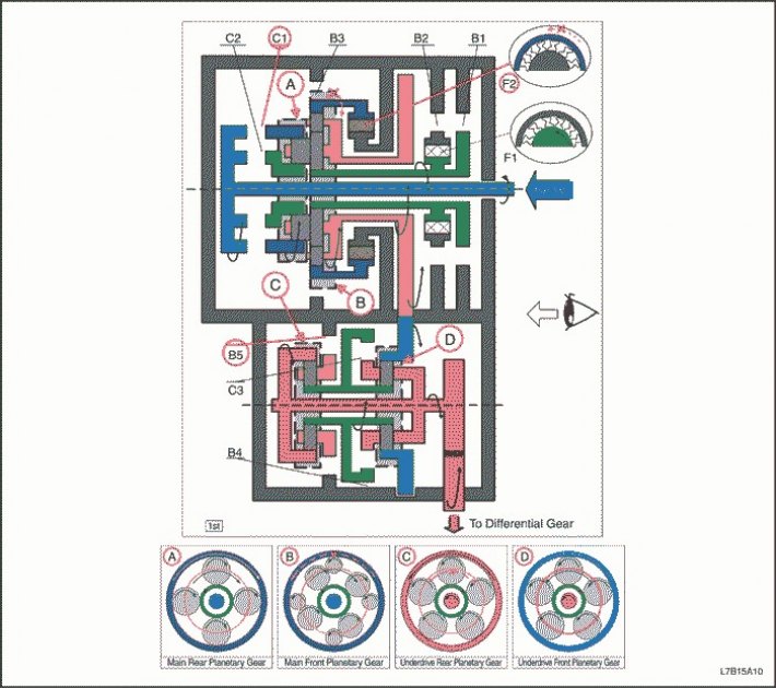
"D" - 1st gear
1. The primary shaft rotates clockwise.
- C1 is on (Connects the primary shaft to the epicyclic gear of the rear planetary row)
2. The epicyclic gear of the rear planetary row rotates clockwise.
3. The rear planetary gear satellite rotates clockwise by itself.
4. The large front planetary gear satellite rotates clockwise itself, and the rear planetary gear satellite rotates with it.
5. The small satellite of the front planetary gear rotates counterclockwise by itself.
6. The front epicyclic gear will rotate counterclockwise.
- F2 is on (Providing counter-clockwise rotation lock for the front planetary gear epicyclic gear).
7. The front and rear planetary gear carrier rotates clockwise due to the reactive force of the small satellite of the front planetary gear.
8. The intermediate shaft drive gear rotates clockwise, and the front and rear planetary gear carrier rotates with it.
9. The intermediate shaft driven gear rotates counterclockwise.
10. The epicyclic gear of the front planetary row rotates counterclockwise, and the driven gear of the intermediate shaft rotates with it.
11. The front planetary gear satellite itself rotates counterclockwise.
12. The front planetary gear sun wheel rotates clockwise.
13. The rear planetary gear sun wheel rotates clockwise, and the front planetary gear sun wheel rotates with it.
14. The rear planetary gear satellite rotates counterclockwise by itself.
- B5 is on (Blocks the rotation of the rear planetary gear carrier).
15. The epicyclic gear of the rear planetary gear set rotates counterclockwise.
16. The front row planet carrier and the differential gear satellite rotate counterclockwise, and the rear epicyclic gear rotates with them.
17. The driven gear of the main transmission rotates clockwise.
(Engine braking)
1. The intermediate shaft drive gear and the main carrier of the front and rear planetary gear sets rotate clockwise.
2. The rear planetary gear carrier rotates clockwise, but the rear planetary gear satellite rotates clockwise, although it itself rotates counterclockwise due to the resistance of the rear planetary gear epicyclic gear.
3. The large satellite of the front planetary gear rotates clockwise, although it itself rotates counterclockwise, and the small satellite of the front planetary gear rotates clockwise, although it itself rotates clockwise. And the carrier of the front planetary row rotates clockwise.
4. The front epicyclic gear rotates clockwise because the front row small satellite itself rotates clockwise, but the driving force is lost due to the release of F2. Therefore, engine braking does not activate.
D - 2nd gear
|
Position
|
Solenoid
|
Coupling
|
Brake
|
Overrunning clutch
|
||||||||||||
|
S1
|
S2
|
S3
|
S4
|
S5
|
C1
|
C2
|
C3
|
B1
|
B2
|
B3
|
B4
|
B5
|
F1
|
F2
|
||
|
D
|
2nd
|
Off.
|
Off.
|
On.
|
Off.
|
Off.
|
On.
|
Off.
|
Off.
|
On.
|
On.
|
Off.
|
Off.
|
On.
|
On.
|
Off.
|
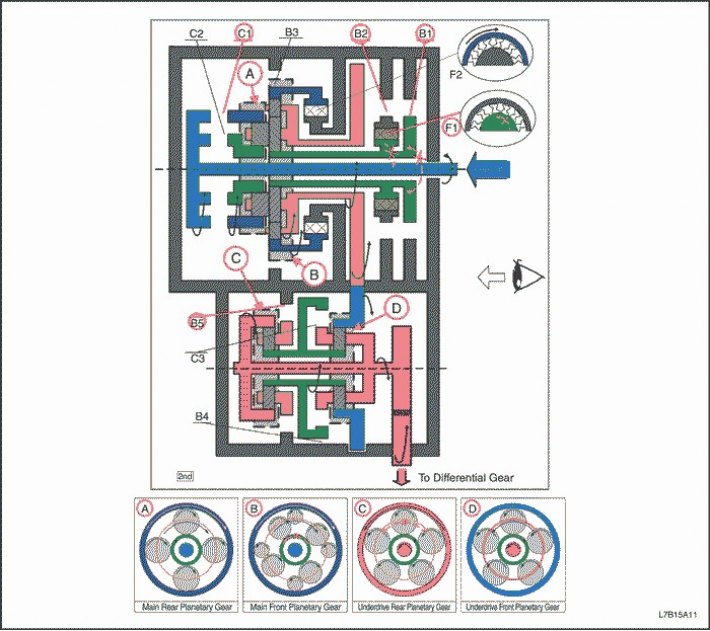
"D" - 2nd gear
1. The primary shaft rotates clockwise.
- C1 is on (Connects the primary shaft to the epicyclic gear of the rear planetary row)
2. The epicyclic gear of the rear planetary row rotates clockwise.
3. The rear planetary gear satellite rotates clockwise by itself.
4. The large front planetary gear satellite rotates clockwise itself, and the rear planetary gear satellite rotates with it.
- B2 with F1 and B1 included (Blocks the rotation of the front planetary gear sun wheel)
5. The front and rear planetary gear carrier rotates clockwise due to the reactive force of the large front planetary gear satellite.
6. The intermediate shaft drive gear rotates clockwise, and the front and rear planetary gear carrier rotates with it.
7. The intermediate shaft driven gear rotates counterclockwise.
8. The epicyclic gear of the front planetary row rotates counterclockwise, and the driven gear of the intermediate shaft rotates with it.
9. The front planetary gear satellite itself rotates counterclockwise.
10. The front planetary gear sun wheel rotates clockwise.
11. The rear planetary gear sun wheel rotates clockwise, and the front planetary gear sun wheel rotates with it.
12. The rear planetary gear satellite rotates counterclockwise by itself.
- B5 is on (Blocks the rotation of the rear planetary gear carrier)
13. The epicyclic gear of the rear planetary gear set rotates counterclockwise.
14. The front row planet carrier and the differential gear satellite rotate counterclockwise, and the rear epicyclic gear rotates with them.
15. The driven gear of the main transmission rotates clockwise.
(Engine braking)
1. The driving force is transmitted to the primary shaft without the intervention of the overrunning clutch. Engine braking works.
D - 3rd gear
|
Position
|
Solenoid
|
Coupling
|
Brake
|
Overrunning clutch
|
||||||||||||
|
S1
|
S2
|
S3
|
S4
|
S5
|
C1
|
C2
|
C3
|
B1
|
B2
|
B3
|
B4
|
B5
|
F1
|
F2
|
||
|
D
|
3rd
|
Off.
|
Off.
|
On.
|
On.
|
Off.
|
On.
|
Off.
|
Off.
|
On.
|
On.
|
Off.
|
On.
|
Off.
|
On.
|
Off.
|
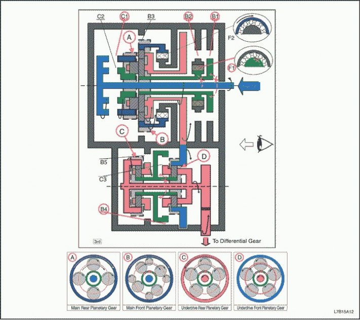
"D" - 3rd gear
1. The primary shaft rotates clockwise.
- C1 is on (Connects the primary shaft to the epicyclic gear of the rear planetary row)
2. The epicyclic gear of the rear planetary row rotates clockwise.
3. The rear planetary gear satellite rotates clockwise by itself.
4. The large front planetary gear satellite rotates clockwise itself, and the rear planetary gear satellite rotates with it.
- B2 with F1 and B1 included (Blocks the rotation of the front planetary gear sun wheel)
5. The front and rear planetary gear carrier rotates clockwise due to the reactive force of the large front planetary gear satellite.
6. The intermediate shaft drive gear rotates clockwise, and the front and rear planetary gear carrier rotates with it.
7. The intermediate shaft driven gear rotates counterclockwise.
8. The epicyclic gear of the front planetary row rotates counterclockwise, and the driven gear of the intermediate shaft rotates with it.
9. The front planetary gear satellite itself rotates counterclockwise.
- B4 included (Blocks the rotation of the sun wheel of the front and rear planetary rows)
10. The front planetary gear carrier rotates counterclockwise due to the reactive force of the front planetary gear satellite.
11. The rear epicyclic gear and differential gear satellite rotate counterclockwise, and the front row planet carrier rotates with them.
12. The driven gear of the main transmission rotates clockwise.
(Engine braking)
- The driving force is transmitted to the primary shaft without the intervention of the overrunning clutch. Engine braking works.
D - 4th gear
|
Position
|
Solenoid
|
Coupling
|
Brake
|
Overrunning clutch
|
||||||||||||
|
S1
|
S2
|
S3
|
S4
|
S5
|
C1
|
C2
|
C3
|
B1
|
B2
|
B3
|
B4
|
B5
|
F1
|
F2
|
||
|
D
|
4th
|
Off.
|
Off.
|
Off.
|
On.
|
Off.
|
On.
|
Off.
|
On.
|
On.
|
On.
|
Off.
|
Off.
|
Off.
|
On.
|
Off.
|
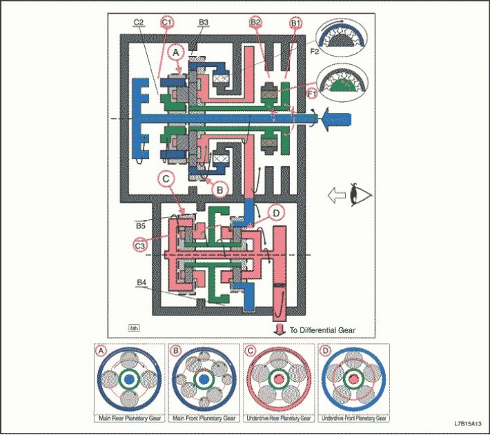
"D" - 4th gear
1. The primary shaft rotates clockwise.
- C1 is on (Connects the primary shaft to the epicyclic gear of the rear planetary row)
2. The epicyclic gear of the rear planetary row rotates clockwise.
3. The rear planetary gear satellite rotates clockwise by itself.
4. The large front planetary gear satellite rotates clockwise itself, and the rear planetary gear satellite rotates with it.
- B2 with F1 and B1 included (Blocks the rotation of the front planetary gear sun wheel)
5. The front and rear planetary gear carrier rotates clockwise due to the reactive force of the large front planetary gear satellite.
6. The intermediate shaft drive gear rotates clockwise, and the front and rear planetary gear carrier rotates with it.
7. The intermediate shaft driven gear rotates counterclockwise.
8. The epicyclic gear of the front planetary row rotates counterclockwise, and the driven gear of the intermediate shaft rotates with it.
- C3 is on (Providing connection between the sun wheel of the planetary gear set and the front planetary gear carrier)
9. The front planetary gear satellite cannot rotate by itself, and the reduction gear unit rotates counterclockwise alone.
10. The differential gear satellite rotates counterclockwise, and the reduction gear unit rotates with it.
11. The driven gear of the main transmission rotates clockwise.
"Engine braking"
1. The driving force is transmitted to the primary shaft without the intervention of the overrunning clutch. Engine braking works.
D-5th gear
|
Position
|
Solenoid
|
Coupling
|
Brake
|
Overrunning clutch
|
||||||||||||
|
S1
|
S2
|
S3
|
S4
|
S5
|
C1
|
C2
|
C3
|
B1
|
B2
|
B3
|
B4
|
B5
|
F1
|
F2
|
||
|
D
|
5th
|
Off.
|
On.
|
Off.
|
On.
|
Off.
|
On.
|
On.
|
On.
|
Off.
|
On.
|
Off.
|
Off.
|
Off.
|
Off.
|
Off.
|
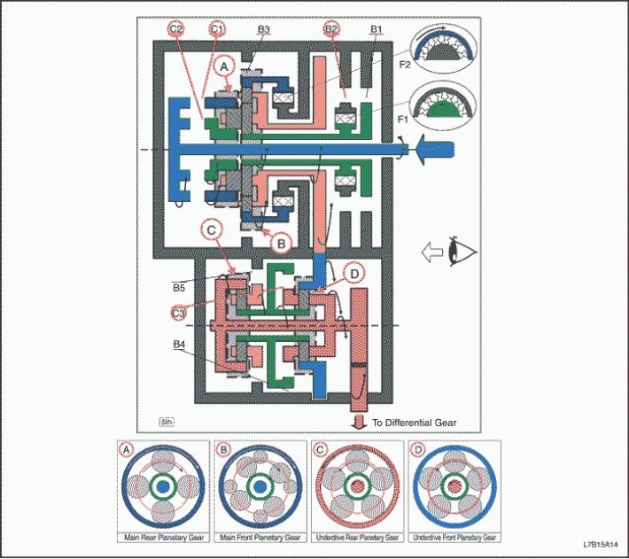
"D" - 5th gear
1. The primary shaft rotates clockwise.
- C1 is on (Connects the primary shaft to the epicyclic gear of the rear planetary row)
- C2 is on (Providing connection between the primary shaft and the rear planetary gear sun wheel)
2. The rear planetary gear satellite cannot rotate by itself, and the rear planetary gear unit rotates clockwise alone.
3. The large front planetary gear pinion cannot rotate itself together with the rear planetary gear pinion, and the front planetary gear block rotates clockwise alone.
4. The intermediate shaft drive gear rotates clockwise, and the front planetary gear unit rotates with it.
5. The intermediate shaft driven gear rotates counterclockwise.
6. The epicyclic gear of the front planetary row rotates counterclockwise, and the driven gear of the intermediate shaft rotates with it.
- C3 is on (Providing connection between the sun wheel of the planetary gear set and the front planetary gear carrier)
7. The front planetary gear satellite cannot rotate by itself, and the reduction gear unit rotates counterclockwise alone.
8. The differential gear satellite rotates counterclockwise, and the reduction gear unit rotates with it.
9. The driven gear of the main transmission rotates clockwise.
"Engine braking"
1. The driving force is transmitted to the primary shaft without the intervention of the overrunning clutch. Engine braking works.
Reverse
|
Position
|
Solenoid
|
Coupling
|
Brake
|
Overrunning clutch
|
||||||||||||
|
S1
|
S2
|
S3
|
S4
|
S5
|
C1
|
C2
|
C3
|
B1
|
B2
|
B3
|
B4
|
B5
|
F1
|
F2
|
||
|
R
|
V≤7 km/h
|
Off.
|
Off.
|
On.
|
Off.
|
On.
|
Off.
|
On.
|
Off.
|
Off.
|
Off.
|
On.
|
Off.
|
On.
|
Off.
|
Off.
|
|
V > 7 km/h
|
On.
|
Off.
|
Off.
|
Off.
|
Off.
|
Off.
|
Off.
|
Off.
|
Off.
|
Off.
|
Off.
|
Off.
|
On.
|
Off.
|
Off.
|
|
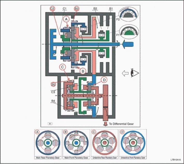
Reverse
1. The primary shaft rotates clockwise.
- C2 is on (Providing connection between the primary shaft and the rear planetary gear sun wheel)
2. The rear planetary gear sun wheel rotates clockwise.
3. The rear planetary gear satellite rotates counterclockwise by itself.
4. The large front planetary gear satellite rotates counterclockwise itself, and the rear planetary gear satellite rotates with it.
5. The small satellite of the front planetary gear rotates clockwise by itself.
- B3 is on (Blocks rotation of the front planetary gear epicyclic gear)
6. The front and rear planetary gear carrier rotates counterclockwise due to the reactive force of the small satellite of the front planetary gear.
7. The intermediate shaft drive gear rotates counterclockwise, and the front and rear planetary gear carrier rotates with it.
8. The intermediate shaft driven gear rotates clockwise.
9. The epicyclic gear of the front planetary row rotates clockwise, and the driven gear of the intermediate shaft rotates with it.
10. The front planetary gear satellite itself rotates clockwise.
11. The front planetary gear sun wheel rotates counterclockwise.
12. The rear planetary gear sun wheel rotates counterclockwise, and the front planetary gear sun wheel rotates with it.
13. The rear planetary gear satellite rotates clockwise by itself.
- B5 is on (Blocks the rotation of the rear planetary gear carrier)
14. The epicyclic gear of the rear planetary row rotates clockwise.
15. The front row planet carrier and the differential gear satellite rotate clockwise, and the rear epicyclic gear rotates with them.
16. The driven gear of the main transmission rotates counterclockwise.
"Engine braking"
1. The driving force is transmitted to the primary shaft without the intervention of the overrunning clutch. Engine braking works.
Control functions of the gearbox controller
Switch control and lock control
According to the shift program, the TCM sends a signal to the electronic valves S1, S2, S3, S4 and S5, which actuate the two-position control "Shift Control", and to the torque converter clutch lock-up pressure regulator solenoid valve (SLU), which actuates the linear control "Lock Control", based on the vehicle speed and throttle opening.
Operation of each solenoid valve
|
Broadcast
|
S1
|
S2
|
S3
|
S4
|
S5
|
|
1st
|
On.
|
On.
|
On.
|
Off.
|
Off.
|
|
2nd
|
Off.
|
Off.
|
On.
|
Off.
|
Off.
|
|
3rd
|
Off.
|
Off.
|
On.
|
On.
|
Off.
|
|
4th
|
Off.
|
Off.
|
Off.
|
On.
|
Off.
|
|
5th
|
Off.
|
On.
|
Off.
|
On.
|
Off.
|
The 55-51LE automatic transmission with final drive assembly does not provide some driving modes that can be selected by the user. Basically, the TCM is programmed for "Economy Mode", but under specific conditions the TCM automatically switches to several shift programs. However, only "Winter Mode" can be selected by the switch.
1. Adaptive Shift Control for the Driver (modes Economy, Average, Sports)
Economy mode is used for normal driving conditions after the ignition is turned on. And the driver's preference is detected by fuzzy logic based on the accelerator operation. This regulator changes the gear shift timing to Economy (low speed), Average (average speed) and Sports (high speed) according to the degree of preference.
|
Start (1) and (2)
|
(1) "D"
|
(2) Vehicle speed ≥ 5 km/h (3 mph)
|
|
Ending (1), or (2), or (3)
|
(1) Except "D"
|
(2) Vehicle speed > 240 km/h (149 mph)
|
|
(3) It was found that the driver prefers "Economy mode"
|
||
2. Winter mode
This mode is used to start the vehicle moving on a slippery road by pressing the winter mode switch. (The car starts moving in 3rd gear)
|
Range
|
Winter
|
|
|
D
|
3(L) ↔ 4(L) ↔ 5(L)
|
|
↔: Up/Down switching, (L): Lock operation
3. Hill climb mode
When the transmission controller detects a hill climb based on the engine torque load and acceleration reduction, this mode changes the gear shift timing in the high-speed section according to the degree of incline and prevents the automatic transmission from actively shifting.
4. Downhill driving mode
When the TCM detects downhill driving based on the increase in acceleration when the accelerator is fully closed, this mode applies moderate engine braking by changing the shift timing in the high-speed section.
5. HOT mode control
This regulator reduces the temperature of the automatic transmission fluid by changing the shift points when it rises excessively. (Automatic transmission fluid temperature > 140°C (284°F))
6. Control "Height"
This regulator compensates for the loss of engine power by setting the shift points at a slightly higher speed range when the vehicle is at high altitude where the air pressure is lower.
7. Cold bias control
This controller compensates for the loss of engine torque by setting the shift points at a slightly higher vehicle speed range when the air temperature is extremely low. (Engine coolant temperature < -30°C (-22°F))
Manual gear shift control (Step-by-Step mode (TAP))
The driver can select his/her favorite gearshift mechanism and enjoy the sporty driving style and feel of a manual transmission by shifting the gear selector lever from the "D" range to the manual transmission position and the M+ range (upshift) / M-(downshifting). But the lock control is activated automatically. The shift control is activated again by shifting from the manual transmission position to the "D" range.
Lock Off Control
This control disables the lock-up action when downshifting or idling and prevents the engine from stalling when the brake pedal is depressed at low speeds.
Upshift/Downshift Learning Management
This regulator learns the pressure on each clutch or brake to reduce shock with each gear change (Increase, Decrease, Mechanical decrease, Coasting down).
"Learning Management Method"
(1) 65°C (149°F) ≤ Oil temperature < 110°C (230°F)
(2) Constantly low throttle opening (approx. 20-30%)
(3) Sufficient switching interval (about 3 sec.)
(4) Repeat each switch about 10 times
ND Switching Control
This controller improves the ND shift quality by controlling the hydraulic line pressure regulating solenoid valve according to the forward clutch (C1) piston stroke learned by the ND learning control and applying the best hydraulic pressure to the forward clutch (C1) during ND shifting.
ND Learning Management
This regulator learns the hydraulic pressure of the forward clutch (1) by monitoring the engagement time and the rotation frequency of the forward clutch (1).
|
Start (1), and (2), and (3) and (4)
|
(1) 500 rpm ≤ Crankshaft speed < 1200 rpm
|
|
|
(2) 65°C (149°F) ≤ Oil temperature < 110°C (230°F)
|
||
|
(3) 450 rpm ≤ forward clutch rotation (C1) < 1200 rpm
|
||
|
(4) Throttle opening < 3.0%
|
||
"Learning Management Method"
(1) When above the launch conditions
(2) Switching interval more than 3 sec.
(3) Repeat ND switching about 10 times
NR Switching Control
This regulator improves the NR shift quality by controlling the shift pressure control solenoid valve according to the piston stroke of the forward clutch (C2) learned by the NR learning control and applying the best hydraulic pressure to the clutch (C2) during NR shifting.
NR Learning Management
This controller learns the hydraulic pressure of the direct drive clutch (C2) by monitoring the engagement time and the rotational speed of the C2 clutch.
|
Start (1), and (2), and (3) and (4)
|
(1) 500 rpm ≤ Crankshaft speed < 1200 rpm
|
|
|
(2) 65°C (149°F) ≤ Oil temperature < 110°C (230°F)
|
||
|
(3) 450 rpm ≤ forward clutch rotation (C1) < 1200 rpm
|
||
|
(4) Throttle opening < 3.0%
|
||
"Learning Management Method"
(1) When above the launch conditions
(2) Switching interval more than 3 sec.
(3) Repeat NR switching about 10 times
Torque reduction control
This controller improves shift quality by sending a torque reduction request signal from the TCM to the ECM and disabling the shift torque boost during ND, NR and 1↔2↔3↔4↔5 shifts.
When the accelerator pedal is depressed quickly, this control sets the upper limit value of engine torque and prevents the condition known as "Brief engine overspeed" when shifting "clutch to clutch" 2↔3, 3↔4 and 4→2.
Adaptive learning procedure of the checkpoint
Perform the gearbox adaptive learning procedure after any of the following maintenance activities:
- Replacing the gearbox controller
- Changing the calibration of the gearbox controller
- Replacing the control valve block
- Major overhaul of gearbox with final drive assembly
- Replacing the gearbox with the main gear assembly
1. Drive the vehicle to warm up the transmission fluid to 65-110°C (150-230°F). The adaptive learning procedure will not be performed if the transmission fluid is not warmed up to the appropriate temperature.
2. Reset the adaptive learning results of the gearbox with the final drive assembly.
3. Complete the following steps to learn garage shifts adaptively.
- Apply the parking brake and press the brake pedal.
- Shift from NEUTRAL to REVERSE for 3 seconds.
- Shift from REVERSE to Neutral range.
- Repeat the above two steps five times.
- Switch from the NEUTRAL range to the DRIVE range for 3 seconds.
- Shift from DRIVE to Neutral.
- Repeat the above two steps five times.
4. Perform the following steps to learn adaptive up/down switching.
- Drive the vehicle in the "DRIVE" range with light throttle (15-20%) until the speed exceeds 50 km/h (31 mph) in 4th gear.
- Reduce engine speed and press the brake until the car comes to a complete stop. Braking the car takes at least 14 seconds.
- Repeat the above steps five times.
5. If the gear shift indicator positions are marked P, R, N, D, 4, 2:
- Perform the following steps to adaptively learn 4→2 mechanical downshifting (Non-step TAP switching).
- Drive the vehicle in range "4" until the speed exceeds 25 km/h (16 mph) in 2nd at any throttle position.
- Slow down, manually shift gear from "4" to "2" and stop the car.
- Repeat the above two steps ten times.
If the gear shift indicator positions are marked P, R, N, D, M:
- Perform the following steps for adaptive learning of step-by-step switching (TAP-DOWN) 2→1 (TAP step switching).
- Drive the vehicle in TAP 2 until the speed exceeds 25 km/h (16 mph) or in 2nd gear at any throttle position.
- Slow down, manually switch from "TAP 2" to "TAP 1" and stop the car.
- Repeat the above two steps ten times.
Important: If shift quality does not improve, make sure the gearbox controller is calibrated correctly.
6. Confirm the quality of switching.