


Contents: Removal ↧ Installation ↧
Removal
1. Remove the drive shaft.
2. Cut off the stamped ring (2) securing the boot to the CV joint housing (1).
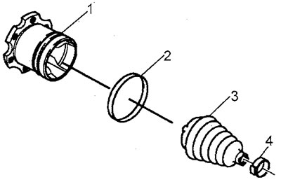
3. Remove the CV joint housing from the shaft rod.
4. Remove grease from the CV joint housing.
5. Rinse the body.
6. The body must be dry during assembly.
7. Cut off the small clamp of the cover.
8. Remove the retaining ring (1), crosspiece (2) and cover (3).
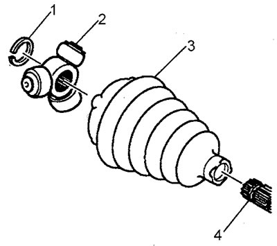
9. Wash the shaft rod (4). Use a wire brush to remove dirt and rust, especially in the area where the boot is installed.
10. Check the condition of the bearing needles and the crosspiece journal. Inspect the CV joint housing, look for signs of wear, cracks and other damage.
Installation
1. Install a new small clamp (2) onto the boot (1). Place the boot and clamp onto the drive shaft rod.
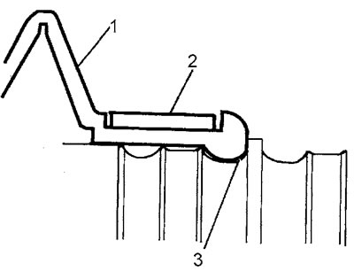
2. Install the cover boss (1) into the groove (3) of the shaft.
3. Tighten the clamp (1) using pliers. The tightening torque of the pliers should be 136 Nm.
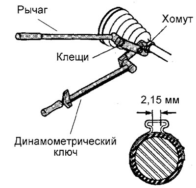
4. Measure the gap in the clamp eye; if the gap is greater than 2.15 mm, tighten the clamp to the required gap.
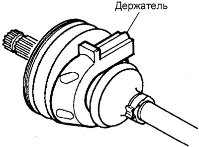
5. Place the fold holder on the cover so that it covers 2-4 folds of the cover.
6. Install the crosspiece (3) of the CV joint onto the shaft rod (2).
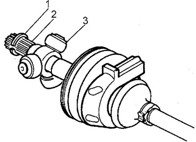
7. Install the retaining ring (1) into the groove of the shaft rod (2).
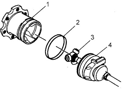
8. Fill the CV joint boot (4) and CV joint housing (1) with grease from the repair kit (the entire volume of lubricant supplied in the kit).
9. Install the boot on the CV joint housing as follows:
- a) Squeeze the stamped ring (2) with your hands so that the ring takes on a slight oval shape.
- b) Place the ring on the cover.
- c) Install the CV joint housing onto the crosspiece.
- d) Install the cover on the CV joint housing.
- d) Install the cover boss (1) into the housing groove (3). The ring (2) must be inserted into the cover groove.
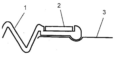
10. Fix the ring compression device in a vice, install the CV joint housing in the device as shown in the figure.
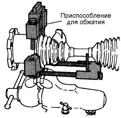
11. Install the upper part of the device.
12. Align the stamped ring (2) and the ring bracket of the device.
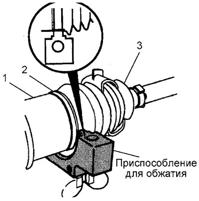
13. Insert the bolts securing the upper part of the device, tighten the bolts by hand.
14. Tighten the bolts alternately by turning them half a turn. Simultaneously align the position of the boot (3), housing (1) and ring (2). Stop tightening after both halves of the device come together. Unscrew the bolts, remove the inner CV joint.
15. Measure the distance "A" and compare the result with the specification data.
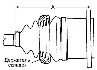
Distance "A":
- series 1500 - 170 mm
- 2500 series - 178 mm
16. Remove the fold holder.
17. Install the drive shaft.