Cooling system
The function of the cooling system is to maintain the engine at an efficient operating temperature at all engine speeds and operating conditions. The cooling system is designed to remove approximately one-third of the heat generated by combustion of the air-fuel mixture. When the engine is cold, no coolant flows to the radiator until the thermostat opens. This allows the engine to warm up quickly.
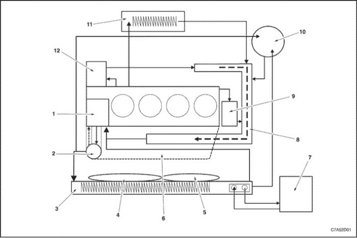
1. Water pump
2. Thermostat
3. Radiator
4. Main cooling system fan
5. Auxiliary cooling fan
6. Intake manifold
7. Gearbox with final drive assembly
8. Water tube
9. Exhaust Gas Recirculation Cooler
10. Expansion tank
11. Heater
12. Oil radiator of the engine cooling system
Water pump
The water pump is a component of the engine cooling system and circulates coolant from each component in the cooling circuit.
This water pump includes a seal, bearing, pulley and housing and is driven from the crankshaft via the reverse side of the timing belt to reduce noise from the water pump pulley.
The water pump is equipped with a drain cover cup to prevent coolant from spilling onto customers.
The water pump does not have an open type impeller, but a closed type plastic impeller to improve cooling efficiency.
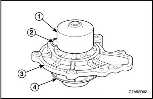
1. Water pump pulley
2. Drain hole cover cup
3. Frame
4. Impeller
Thermostat
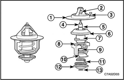
The thermostat regulates the flow of coolant and is mounted on the intake manifold. Depending on the coolant temperature, the wax bead of the thermostat mechanically stretches or compresses the mainspring, allowing the coolant to flow.
The thermostat begins to open at 80°C (176°F) and is fully open at 95°C (203°F). The thermostat closes at 75°C (167°F).
1. Saddle
2. Cap
3. Float valve
4. Piston
5. Retaining ring
6. Rubber valve
7. Element in assembly
8. Mainspring
9. Bypass shaft
10. Frame
11. Bypass spring
12. Bypass valve
13. Retaining ring
Radiator
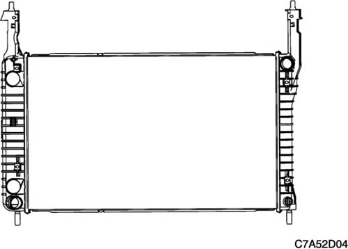
The radiator is a heat exchanger. It consists of a core and two tanks. The aluminum core is a cross-flow structure of tubes and plates that extends from the inlet tank to the outlet tank. The plates are located around the outside of the tubes to improve heat exchange with the atmosphere.
The inlet and outlet tanks are molded from heat-resistant, polyamide fiber-reinforced plastic. A heat-resistant rubber gasket serves as a seal between the flanged edge of the tank and the aluminum core. The tanks are secured to the core by tabs with clips. The tabs are part of the aluminum manifold at each end of the core.
The radiator also has a drain plug, which is located at the bottom of the left tank. The drain plug assembly includes the drain plug itself and the drain plug seal.
The radiator removes heat from the coolant that passes through it. Fins on the core transfer heat from the coolant through tubes. Air passes between the fins, absorbing heat and cooling the coolant.
Expansion tank
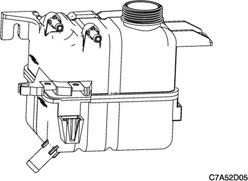
The expansion tank is a plastic tank with a threaded, sealed cap. The tank is mounted at a point above all other coolant passages. The expansion tank provides an air space in the cooling system that allows the coolant to expand and contract. The expansion tank serves as a coolant fill point and a venting center.
As the vehicle is used, the coolant heats up and expands. The increasing volume of coolant flows into the expansion tank. As the coolant circulates, all the air is allowed to bubble out. Coolant without air bubbles absorbs heat much better than coolant with bubbles.
Cooling system fan
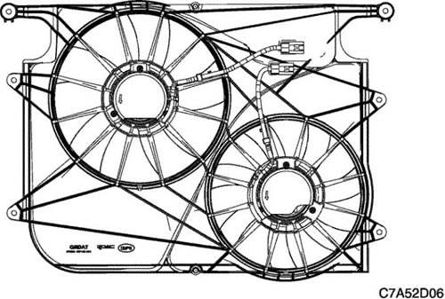
Cooling fans are mounted behind the radiator in the engine compartment. The engine cooling fan is electrically powered. The cooling fan draws air through the radiator to improve the transfer of heat from the coolant to the atmosphere. As the fan blades rotate, they increase the flow of air through the radiator core and through the condenser on vehicles with air conditioning. This allows for faster cooling at idle or low speeds.