


If one of the circuits of the service brake system fails, another circuit is used, ensuring that the vehicle stops with sufficient efficiency.
The hydraulic drive includes the main brake cylinder 23 (Fig. 9.1), vacuum booster 5, hydroelectronic module 22 of the anti-lock braking system, brake mechanisms of the front and rear wheels together with the working cylinders, and pipelines.
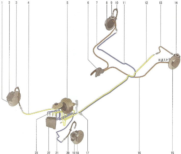
Fig. 9.1. Brake system: 1 - brake disc of the right front wheel; 2 - brake mechanism of the right front wheel; 3 - flexible hose of the brake mechanism of the right front wheel; 4 - right front wheel brake line; 5 - vacuum booster; 6 - parking brake lever; 7, 16 - parking brake drive cables; 8 - brake disc of the right rear wheel; 9 - brake mechanism of the right rear wheel; 10 - flexible hose of the brake mechanism of the right rear wheel; 11 - right rear wheel brake mechanism pipeline; 12 - left rear wheel brake mechanism pipeline; 13 - flexible hose of the brake mechanism of the left rear wheel; 14 - brake mechanism of the left rear wheel; 15 - left rear wheel brake disc; 17 - brake pedal; 18 - left front wheel brake mechanism; 19 - brake disc of the brake mechanism of the left front wheel; 20 - flexible hose of the brake mechanism of the left front wheel; 21 - left front wheel brake mechanism pipeline; 22 - ABS hydroelectronic module; 23 - master brake cylinder
Parking brake system with cable drive on the rear wheel brake mechanisms.
The front wheel brake mechanism is a disc brake with automatic adjustment of the gap between the shoes 10 (Fig. 9.2) and the disk 1, with a floating caliper. The movable caliper is formed by the support 11 with a single-piston working cylinder. The guide 2 of the shoes is attached with bolts to the steering knuckle. The support is attached with bolts 4 and 7 to the guide pins installed in the holes of the shoe guide. The guide pins are lubricated with consistent grease and protected by rubber boots. A piston with a sealing ring is installed in the cavity of the wheel cylinder. Due to the elasticity of this ring, an optimal gap is maintained between the shoes and the ventilated disk, the surface of which is protected by a brake shield. When braking, the piston, under the influence of fluid pressure, presses the inner pad to the disk, as a result of the reaction force, the caliper moves on the fingers and the outer pad is also pressed to the disk, while the pressing force of the pads is the same. When releasing the brakes, the piston is moved away from the pad due to the elasticity of the sealing ring; a small gap is formed between the pads and the disk.
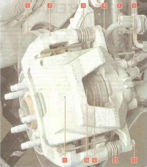
Fig. 9.2 Front wheel brake mechanism: 1 - brake disc; 2 - shoe guide; 3, 8 - protective covers of guide pins; 4, 7 - caliper guide pin mounting bolts; 5 - brake hose; 6 - air release valve; 9 - brake cylinder piston dust cover; 10 - brake shoe; 11 - brake caliper
The main brake cylinder 4 (Fig. 9.3) of the "tandem" type of the hydraulic brake drive consists of two separate chambers connected to independent hydraulic circuits. The first chamber is connected to the right front and left rear brake mechanisms, the second to the left front and right rear.
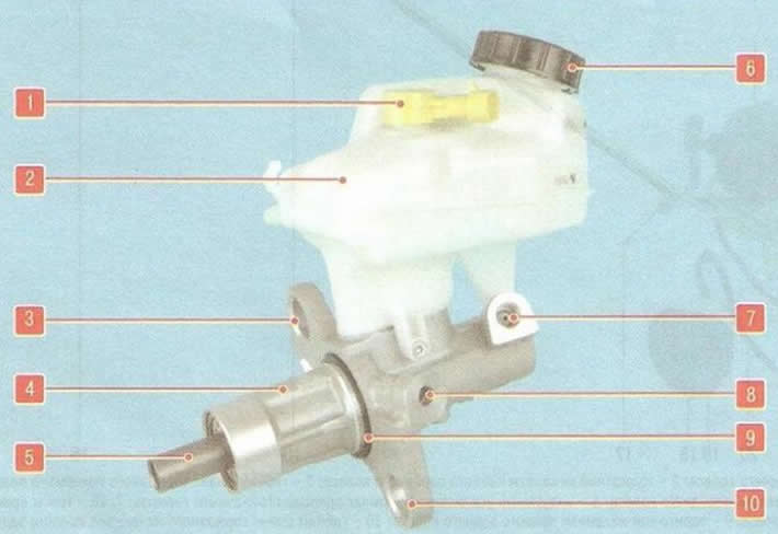
Fig. 9.3. Master brake cylinder with reservoir: 1 - brake fluid level sensor; 2 - master brake cylinder reservoir; 3, 10 - cylinder mounting flange lugs; 4 - brake cylinder housing; 5 - piston pusher; 6 - tank cap; 7, 8 - connecting holes of pipelines; 9 - sealing ring
A reservoir 2 is installed on the master cylinder via rubber connecting bushings, the internal cavity of which is divided by partitions into three sections. Each section supplies one of the chambers of the master brake cylinder and the master cylinder of the clutch release drive.
When you press the brake pedal, the pistons of the master brake cylinder begin to move, the working edges of the cuffs cover the compensation holes, the chambers and the reservoir are separated and the displacement of the brake fluid begins.
The tank body contains a brake fluid level sensor 1. When the fluid level drops below the permissible level, the brake system malfunction indicator light comes on in the instrument cluster.
The vacuum booster, installed between the pedal mechanism and the main brake cylinder, during braking, due to the vacuum in the engine intake pipe through the rod and piston of the first chamber of the main cylinder, creates additional force proportional to the force from the pedal.
A check valve is installed in the hose connecting the vacuum booster to the intake pipe. It holds the vacuum in the booster when it drops in the intake pipe.
The vacuum brake booster is the most common type of booster used in the brake system of a modern car. It creates additional force on the brake pedal due to vacuum. Using a booster significantly facilitates the work of the car's brake system and thus reduces driver fatigue.
Structurally, the vacuum booster forms a single unit with the master brake cylinder.
Note: Replacement of the vacuum booster is not described in this section due to the fact that when performing this operation it is necessary to remove the ABS electronic unit. It is recommended that work on removing the electronic unit be carried out in specialized service centers.
The rear wheel brake mechanism is disc, with automatic clearance adjustment. Brake pads 9 and 10 (Fig. 9.4) are driven by one hydraulic working cylinder. The optimum clearance between the disk and pads is maintained according to the same principle as the front wheel brake mechanisms.
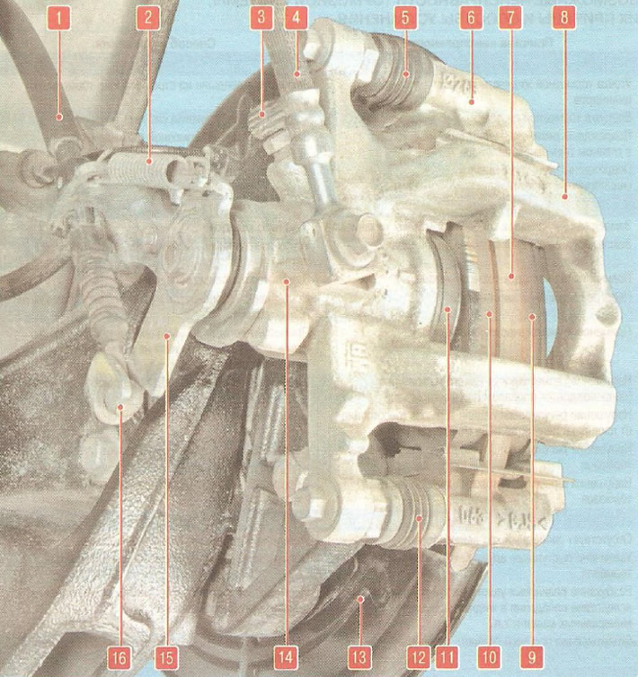
Fig. 9.4 Rear wheel brake mechanism: 1 - parking brake drive cable; 2 - return spring of the parking brake mechanism; 3 - air release valve; 4 - brake hose; 5, 12 - caliper guide pins; 6 - shoe guide; 7 - brake disc; 8 - brake caliper; 9, 10 - brake pads; 11 - dust cover of the working cylinder piston; 13 - brake mechanism shield; 14 - working cylinder; 15 - parking brake lever; 16 - drive cable tip
The rear wheel disc brake mechanism is combined with the parking brake mechanism. The inner cavity of the brake disc simultaneously serves as the parking brake disc.
The mechanically actuated parking brake mechanism consists of a lever, an adjusting device, two rear cables and brake mechanisms on the rear wheels.
The anti-lock braking system (ABS) consists of wheel speed sensors, a switch on the brake pedal, a hydraulic electronic control unit (HECU) and a warning light in the instrument cluster. The anti-lock braking system is also equipped with a self-diagnosis system that detects malfunctions of the system components.
ABS is used to regulate the pressure in the brake mechanisms of all wheels when braking in difficult road conditions, preventing wheel locking.
The ABS system provides the following benefits:
- avoiding obstacles with a higher degree of safety, including during emergency braking;
- reducing the braking distance during emergency braking while maintaining the vehicle's directional stability and controllability, including when turning.
In case of system failure, diagnostic functions and system failure support are provided.
The hydroelectronic control module receives information about the vehicle speed, direction of travel and road conditions from the wheel speed sensors, steering angle sensor and throttle position sensor. After the ignition is turned on, the control unit supplies voltage to the wheel speed sensors. The sensors use the Hall effect, they generate an output signal in the form of rectangular pulses. The signal changes proportionally to the speed of the pulse ring of the sensor, installed on the housing of the outer joint of the wheel drive.
Based on this information, the control unit determines the optimal wheel braking mode.
The following operating modes of the anti-lock braking system are distinguished:
- normal braking mode. During normal braking, the electromagnetic valve is de-energized, the inlet valve is open, and the outlet valve is closed. When the brake pedal is pressed, the brake fluid under pressure is supplied to the working cylinder through the electromagnetic valve and activates the wheel brake mechanisms. When the brake pedal is released, the brake fluid returns to the main brake cylinder through the inlet and check valves;
- emergency braking mode. If the wheel starts to lock during emergency braking, the module issues a command to the electromagnetic valve to reduce the supply of brake fluid, then voltage is supplied to each electromagnetic valve. The inlet valve closes, and the supply of brake fluid from the master cylinder is cut off; the outlet valve opens and brake fluid flows from the slave cylinder to the master cylinder and then to the reservoir, causing a decrease in pressure;
- pressure maintenance mode. When the pressure in the working cylinder drops to the maximum, the module issues a command to the electromagnetic valve to maintain the brake fluid pressure, voltage is supplied to the input valve and is not supplied to the output valve. In this case, the input and output valves are closed and the brake fluid does not leave the working cylinder;
- pressure increase mode. If the module determines that the wheel is not locked, it de-energizes the electromagnetic valve. Voltage is not supplied to the electromagnetic valves, the brake fluid enters the working cylinder through the inlet valve, the pressure in which increases.
Special equipment and tooling are required to diagnose and repair the anti-lock braking system. Therefore, if it fails, contact a specialized service station.
Helpful Hints: Too small a working stroke indicates incorrect initial setting of the brake pedal, incorrect adjustment of the brake booster or jamming of the working cylinder, causes increased fuel consumption and accelerated wear of the brake pads. Too large a working stroke is a sign of excessive clearances in the pedal mechanism or a violation of the tightness of the hydraulic drive of the brake system. If the working stroke decreases with repeated pressing of the pedal, i.e. it becomes "harder", there is air in the system. If the full pedal stroke begins to increase, the system is not tight.
If the brake pedal always starts to vibrate when braking, the brake discs are most likely warped. Unfortunately, in this situation, they only need to be replaced, and both at once. Periodically appearing and disappearing vibration of the pedal during sharp braking accompanies the operation of the anti-lock braking system and is not a sign of a malfunction.
If the car starts to pull to one side when braking, check the wheel cylinders: they may need to be replaced.
If a knocking noise appears in the front suspension that disappears when braking, check the tightness of the caliper mounting bolts.
Original version of the article on the website chevyman.ru