


If one of the circuits of the service brake system fails, the second circuit is used, ensuring that the vehicle stops with sufficient efficiency.
The hydraulic drive includes a vacuum booster. The car is equipped with an anti-lock braking system (ABS), an electronic brake force distribution system (EBD) and an emergency brake assist system (Brake Assist).
Parking brake system - with cable drive to the brake mechanisms of the rear wheels.
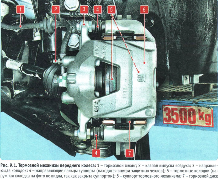
Front wheel brake mechanism disc, with automatic adjustment of the gap between the pads 5 (figure 9.1) and a disk 7, with a floating bracket. The movable (floating) bracket is a support 6 with a single-piston working cylinder. The guide 3 of the pads is attached with bolts to the steering knuckle. The movable bracket is attached with guide pins 4, screwed into the threaded holes of the guide of the pads. The guide pins are lubricated with consistent grease and protected by rubber corrugated covers. A piston with a sealing ring is installed in the cavity of the working cylinder. Due to the elasticity of this ring, an optimal gap is maintained between the pads and the ventilated disk. When braking, the piston, under the pressure of the liquid, presses the inner pad to the disk, under the influence of the reaction force, the caliper moves on the pins and the outer pad is also pressed to the disk, while the pressing forces of the pads are the same. When releasing the brakes, the piston is moved away from the pad due to the elasticity of the sealing ring, resulting in a small gap being formed between the pads and the disc.
Master brake cylinder the tandem type of hydraulic brake drive is installed in the engine compartment directly on the brake booster.
It consists of two separate chambers connected to independent hydraulic circuits. The first chamber is connected to the right front and left rear brake mechanisms, the second - to the left front and right rear.
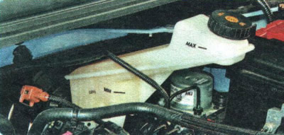
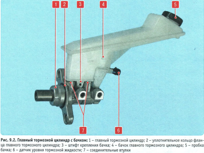
To the master cylinder through rubber connecting bushings 7 (figure 9.2) tank 4 is installed, the internal cavity of which is divided by partitions into three sections. Each section supplies one of the chambers of the main brake cylinder and the main cylinder of the clutch release drive (only on cars with manual transmission).
When you press the brake pedal, the pistons of the master brake cylinder begin to move, the working edges of the cuffs cover the compensation holes, the chambers and the reservoir are separated and the displacement of the brake fluid begins.
The brake fluid level sensor 6 is installed in the lower half of the reservoir body. When the fluid level drops below the permissible level, the brake system malfunction indicator lamp lights up in the instrument cluster. The connection of the master brake cylinder with the brake booster is sealed with a rubber ring 2.
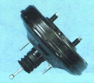
Vacuum booster, installed between the pedal mechanism and the main brake cylinder, during braking, due to the vacuum created by the vacuum pump, as well as the vacuum in the engine intake pipe through the rod and piston of the first chamber of the main cylinder, creates additional force proportional to the force from the pedal.
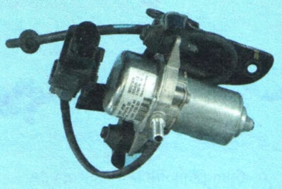
Vacuum pump with an electric drive is installed on the left side member of the engine compartment and creates a constant vacuum necessary for the operation of the brake booster when the vacuum in the engine intake pipe drops during its operation in power modes, as well as when the engine is not running.
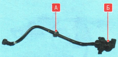
A check valve A is installed in the combined hose connecting the vacuum booster with the vacuum pump and the engine intake pipe. It maintains the vacuum in the booster when it drops after the ignition is turned off. An electrically controlled two-way valve B is installed in the same hose, with the help of which the electronic engine control unit, depending on the engine operating modes, switches the vacuum supply to the brake vacuum booster either from the engine intake pipe or from the vacuum pump.
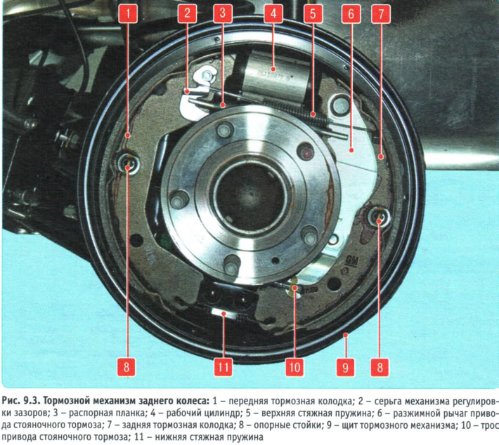
Rear wheel brake mechanism drum, with automatic adjustment of the gap between the shoes and the drum. Brake shoes 1 and 7 (figure 9.3) are driven by one hydraulic working cylinder 4 with two pistons. The optimum clearance between the drum and the shoes is maintained by a mechanical regulator mounted on the spacer bar 3. As the shoe linings wear, the earring 2 turns the regulator nut and its threaded tip lengthens, compensating for the increasing clearance between the spacer bar and the edge of the front shoe.
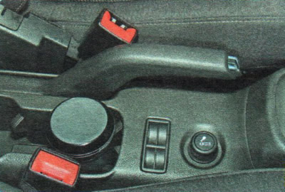
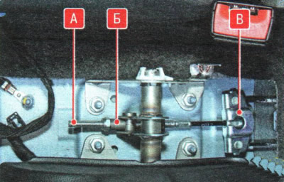
Parking brake, mechanically operated, consists of a lever mounted on the base of the body between the front seats...
...and the front cable A (the floor tunnel lining has been removed for clarity) with adjusting device B and equalizer B, to which two rear cables are connected. The ends of the rear cables are connected to the release levers of the rear wheel brake mechanisms. The release levers act on the rear brake shoes 7 (see figure 9.3) after the front shoes 1 have rested against the brake drum through the spacer bar 3.
The parking brake drive cable 10, being stretched, turns the expansion lever 6 and through the spacer bar 3 presses the front shoe to the brake drum. Having received a rigid stop against the spacer bar, the expansion lever presses the rear shoe 7 to the brake drum. After the parking brake lever is lowered, the shoes move away from the drum under the action of the tension springs 5 and 11.
The parking brake does not require any special maintenance.
Anti-lock braking system (ABS) consists of wheel speed sensors, a brake light switch, a hydroelectronic control unit and a warning lamp. In addition, the anti-lock braking system is equipped with a self-diagnostic system that detects faults in its components and provides functions for maintaining operation in the event of system failures.
ABS is used to regulate the pressure in the brake mechanisms of all wheels when braking in difficult road conditions, which prevents the wheels from locking.
The operating modes of the anti-lock braking system are described in detail in section. "Anti-lock braking system (ABS)".
Special equipment and tooling are required to diagnose and repair the anti-lock braking system. Therefore, if it fails, contact a specialized service station.
The hydraulic brake system is connected into a single unit by metal tubes and hoses. The system is filled with DOT-4 brake fluid.
The procedure for replacing brake fluid is described in the subsection "Replacing brake fluid in the brake hydraulic drive", p. 195.
Checking the brake system is discussed below.
USEFUL TIPS: Some drivers, in an effort to reduce wear on the parking brake cables, try to use it less often.
Such "savings" lead to the opposite result: the cable, rarely moving in the casing, gradually loses mobility, it jams, and as a result the cable breaks. Therefore, use the parking brake in all cases when it is necessary. The working stroke of the brake pedal with the engine running should be approximately 60-65 mm. Too small a working stroke indicates an incorrect initial setting of the brake pedal, a violation of the adjustment of the brake booster or jamming of the working cylinder, causes increased fuel consumption and accelerated wear of the brake pads. Too large a working stroke is a sign of excessive gaps in the pedal mechanism or a violation of the tightness of the hydraulic drive of the brake system. If the working stroke decreases with repeated pressing of the pedal, i.e. it becomes "harder", there is air in the system. If the full pedal stroke begins to increase, the system is not tight.
If the brake pedal always starts to vibrate when braking, the brake discs are most likely warped. Unfortunately, in this situation, they only need to be replaced, and both at once. Periodically appearing and disappearing vibration of the pedal during sharp braking of a car equipped with an anti-lock braking system accompanies the operation of this system and is not a sign of a malfunction.
If the car starts to pull to one side when braking, check the wheel cylinders: they may need to be replaced.
If a knocking noise appears in the front suspension that disappears when braking, check the tightness of the caliper mounting bolts.
After replacing the brake pads, before starting to move, be sure to press the brake pedal several times - the pistons in the working cylinders should fall into place.