


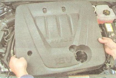
To facilitate access to the sensors, remove the decorative engine cover (see "Removal and installation the decorative engine cover").
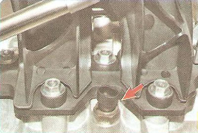
Coolant temperature sensor is installed on the right side of the cylinder head between the 1st and 2nd cylinders. The sensor is a thermistor with a negative temperature coefficient: the electrical resistance of the sensor decreases with increasing temperature. The controller processes the sensor signal and sets the optimal enrichment of the working mixture when the engine warms up.
The resistance of the coolant temperature sensor at its terminals is checked at various temperature conditions.
You will need: a 19 mm wrench, a tester, and a thermometer.
1. Disconnect the wire from the negative terminal of the battery.
2. Drain the coolant (see "Replacing the coolant").
Helpful tip: You don't have to drain the coolant; after removing the sensor, just plug the hole with your finger or a plug, then the loss of coolant will be minimal.
3. Press the retainer and disconnect the wiring harness connector from the coolant temperature sensor.
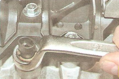
4. Loosen the sensor tightening with a wrench...
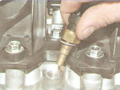
5. ...and unscrew it from the cylinder head.
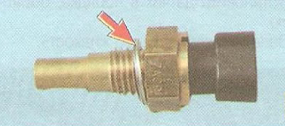
Note: The sensor connection to the cylinder head is sealed with a washer. Replace a washer that is too tight.
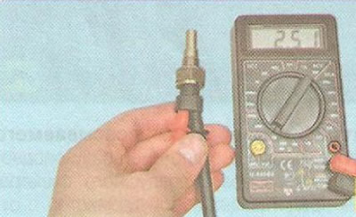
6. Cool the sensor to the ambient temperature. Connect the tester in ohmmeter mode to the sensor terminals and measure its resistance. Measure the current air temperature with a thermometer and compare the obtained values with the data in Table 10.6. If the resistance deviates from the norm, replace the sensor.
Table 10.6. Coolant temperature sensor resistance versus temperature
| Temperature,°C | Sensor resistance, Ohm |
| 100 | 176 |
| 90 | 246 |
| 80 | 327 |
| 70 | 441 |
| 60 | 603 |
| 50 | 837 |
| 40 | 1180 |
| 30 | 1700 |
| 20 | 2500 |
| 10 | 3760 |
| 0 | 5800 |
| -5 | 7273 |
| -10 | 9200 |
| -15 | 11722 |
| -20 | 15 080 |
| -30 | 25 600 |
| -40 | 45 300 |
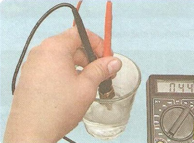
7. To measure the resistance at the sensor terminals at different temperature conditions, lower the sensor into hot water and check the change in its resistance as the water cools, monitoring the water temperature with a thermometer. The nominal resistance values at different temperatures are given in Table 10.6.
8. Install the sensor in the reverse order of removal.
9. Fill with coolant.
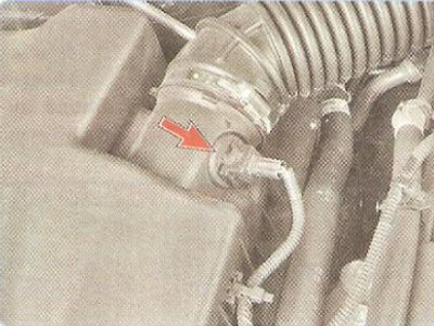
Intake air temperature sensor screwed into the hole of the air supply hose near the air filter. The sensor is a thermistor with a negative temperature coefficient of resistance. Based on the air temperature information from the sensor, the controller regulates the amount of fuel injected.
The air temperature sensor's resistance is checked at its terminals under various temperature conditions.
1. Turn off the ignition.
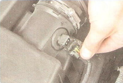
2. Compress the spring clip and disconnect the wiring harness connector from the sensor.
3. Connect the tester in voltmeter mode to the terminals of the wiring harness connector, turn on the ignition and measure the sensor supply voltage. The voltage should be (5±0.2) V.
4. Unscrew the sensor.
5. Connect the tester in ohmmeter mode to the sensor terminals and measure its resistance. Measure the current air temperature with a thermometer and compare the obtained values with the data in Table 10.7. If the resistance deviates from the norm, replace the sensor.
Table 10.7. Dependence of the resistance of the intake air temperature sensor on the temperature
| Temperature,°C | Sensor resistance, Ohm |
| 100 | 176 |
| 90 | 240 |
| 80 | 331 |
| 70 | 466 |
| 60 | 668 |
| 50 | 977 |
| 40 | 1631 |
| 30 | 2238 |
| 20 | 3515 |
| 10 | 5672 |
| 0 | 3452 |
| -5 | 12 291 |
| -10 | 16160 |
| -15 | 21427 |
| -20 | 28 660 |
| -30 | 52705 |
| -40 | 100 780 |
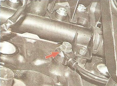
Knock sensor attached to the top of the cylinder block.
You will need a 14 mm wrench.
1. Disconnect the wire from the negative terminal of the battery.
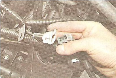
2. Press the spring clip and disconnect the knock sensor wiring harness connectors.
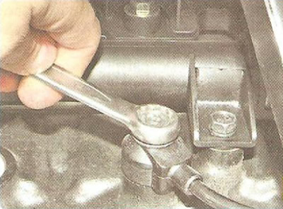
3. Use a wrench to loosen the bolt securing the sensor to the engine cylinder block...
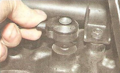
4. ...and, having unscrewed the bolt by hand, remove the knock sensor.
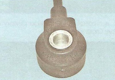
Note: Please pay attention to the marking of the sensor in order to purchase a similar knock sensor for replacement.
5. Install the knock sensor in the reverse order. Tighten the sensor mounting bolt to 20 N·m.
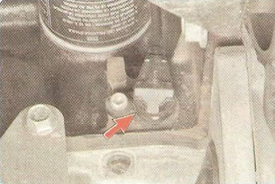
Engine Crankshaft Position Sensor, consisting of a magnet and a winding, is installed at the rear of the engine cylinder block.
If a fault occurs in the crankshaft position sensor circuit, the engine stops running, the controller stores a fault code in memory and turns on the indicator lamp in the instrument cluster. In this case, check the sensor for proper operation.
You will need: a 5 mm Allen key, a tester.
1. Disconnect the wire from the negative terminal of the battery.
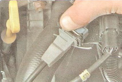
2. Compress the spring clip...
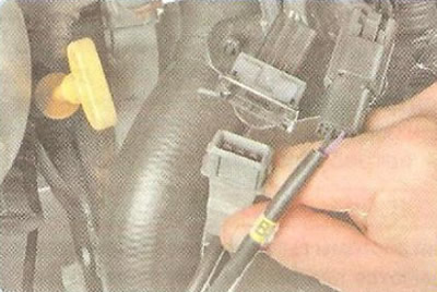
3. ...and disconnect the crankshaft position sensor wiring harness connector.
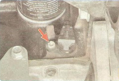
4. Loosen the screw securing the sensor to the engine cylinder block and remove the sensor from the cylinder block hole.
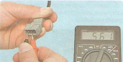
5. Connect the tester probes and measure the resistance at terminals "1" and "2" of the sensor. The nominal resistance value should be within 500-600 Ohms. If the resistance does not meet the specified limits, replace the sensor.
6. Install the crankshaft position sensor in the reverse order of removal.
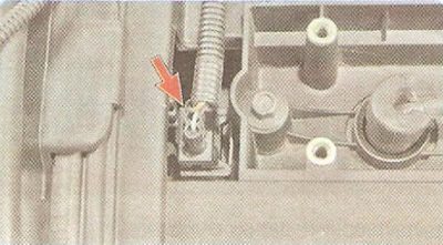
Phase sensor is installed in the front part of the cylinder head between the toothed pulleys of the camshafts. Its operating principle is based on the Hall effect. On the camshaft pulley (graduation) the master segment is completed. When the pulley area without a segment is opposite the sensor, a low-level signal is sent from the sensor to the ECU (approximately 0 V), and when the sector enters the measuring area of the sensor, a "reference" voltage pulse is generated on the ECU (about 5 V).
You will need: a 10 mm wrench, a flat-blade screwdriver.
1. Disconnect the wire from the negative terminal of the battery.
2. Remove the upper timing cover (see "Checking the timing belt").
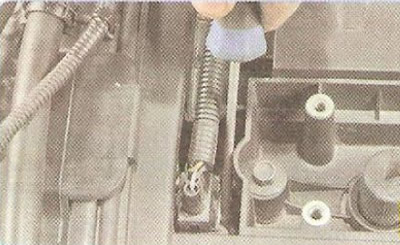
3. Press the lock of the wiring harness connector...
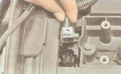
4. ...and disconnect the connector from the phase sensor connector.
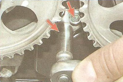
5. Unscrew the two mounting bolts and remove the phase sensor.
6. Install the sensor in the reverse order of removal.
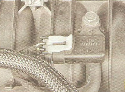
Manifold Absolute Pressure Sensor mounted on the intake pipe. The sensor records the pressure change (rarefaction) in the intake pipe depending on the load and engine crankshaft speed and converts it into an output signal voltage. The ECU supplies the sensor with a supply voltage of 5 V and processes its signals coming through the signal transmission circuit. The sensor is connected to the "ground" through its variable resistor. Depending on the sensor signal, the ECU calculates the amount of air entering the engine.
You will need: a 10 mm wrench, a voltmeter.
1. Check the sensor power supply circuit. To do this...
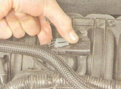
2. ...press the latch...
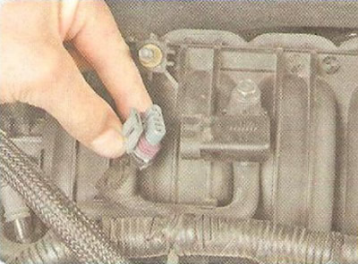
3. ...and disconnect the wiring harness connector from the sensor connector (with ignition off).
4. Connect the tester in voltmeter mode to terminals "A" and "C" of the connector, turn on the ignition and measure the voltage. The supply voltage should be (5.0±0.2) V,
5. Turn off the ignition, remove the cover from the block by pressing the clamps, and connect the block to the sensor.
6. Connect the tester in voltmeter mode to the harness wire connected to terminal "B" and to "ground", start the engine, measure the sensor voltage. When the engine is idling, the voltage should be from 1.0 to 1.5 V.
7. If the voltage deviates from the norm, replace the absolute pressure sensor. To do this, disconnect the vacuum hose from the sensor fitting, unscrew the mounting bolt and remove the sensor.
8. Install the absolute pressure sensor in the reverse order of removal.
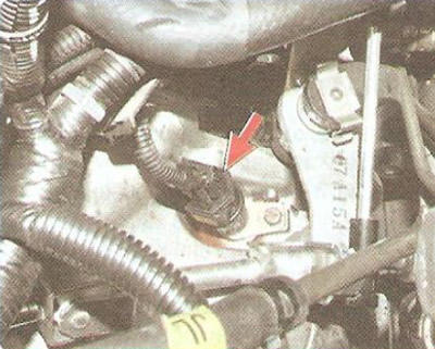
Speed sensor the car is installed on the gearbox.
You will need a 10 mm socket wrench.
1. Disconnect the wire from the negative terminal of the battery.
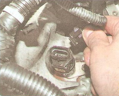
2. Press the lock of the wiring harness connector and disconnect the connector from the speed sensor.
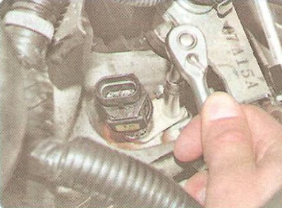
3. Unscrew the mounting bolt...
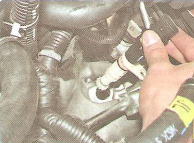
4. ...and remove the sensor together with the drive from the gearbox hole.
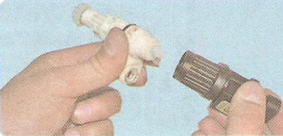
5. Unscrew the sensor from the drive.
6. Install the speed sensor in the reverse order of removal.
To replace the oxygen concentration control sensor perform the following operations.
You will need: keys "12" and "22".
Warning: Exhaust system components become very hot when the engine is running. Be careful when replacing the oxygen sensor! Allow the components to cool.
1. Disconnect the wire from the negative terminal of the battery.
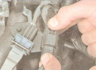
2. Squeeze the latch...
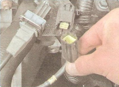
3. ...and disconnect the oxygen concentration sensor control harness connector.
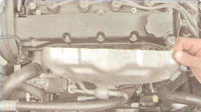
4. Remove the exhaust manifold heat shield (see "Removal and installation of thermal screens"), passing the wire harness with the connector through the hole in the screen.
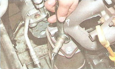
5. Loosen the sensor...
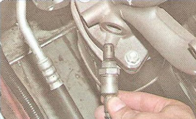
6. ...and unscrew the sensor from the exhaust manifold.
7. Install the oxygen concentration control sensor in the reverse order of removal.
For replacement diagnostic oxygen concentration sensor perform the following operations.
You will need a 22 mm wrench.
Warning: Exhaust system components become very hot when the engine is running. Be careful when replacing the oxygen sensor! Allow the components to cool.
1. Disconnect the wire from the negative terminal of the battery.
2. Place the vehicle on a lift or inspection pit.
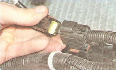
3. Press the release button and disconnect the oxygen sensor diagnostic harness connector.
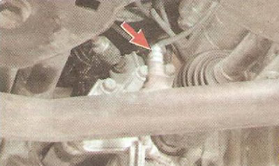
4. Use a wrench to loosen the sensor and unscrew the sensor from the exhaust pipe.
5. Install the oxygen sensor in the reverse order of removal.
(The article was borrowed from the website ChevyMan)