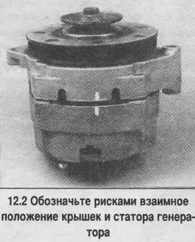
2. Mark the relative positions of the covers and the generator stator with marks to facilitate assembly (see photo).
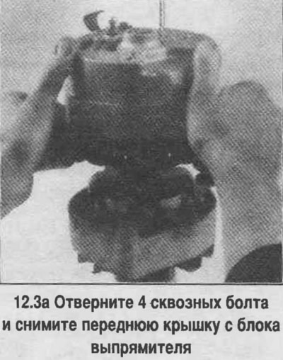
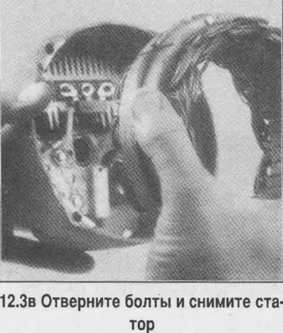
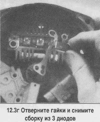
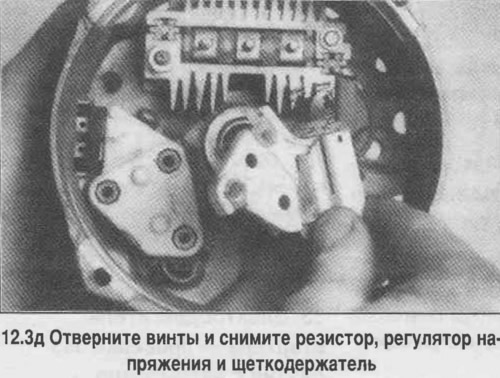
3. Disassemble the generator according to the photo and remove the voltage regulator and brushes.
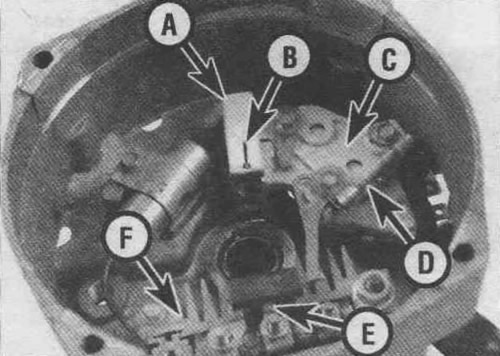
12.36. The front part of the SI generator:
A. Brush holder
B. Brush grip clip
C. Voltage regulator
D. Resistor (provided on some generators)
E. Assembly of 3 diodes
F. Rectifier
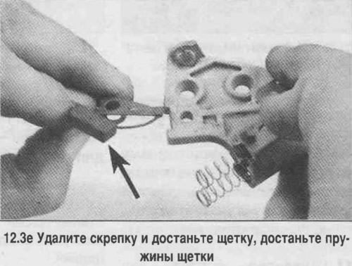
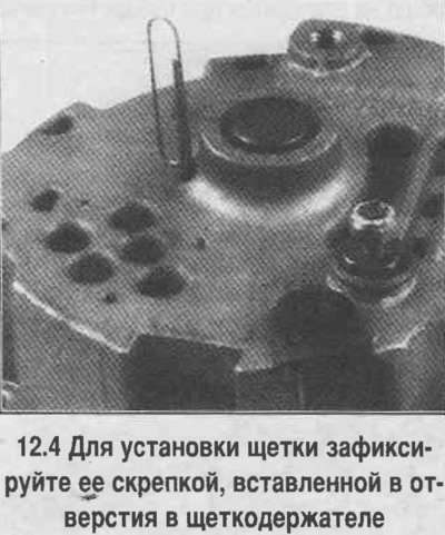
4. Assembly is carried out in the reverse order. Note that the brush fixing clip should be removed only after the final assembly of the generator housing.