
ChevyMan.ru
Mazda Mitsubishi Toyota Land Rover Honda Kia Nissan
English Русский
Български
Беларускі
Український
Српски
Hrvatski
Română
Polski
Slovenský
Magyar
|
Articles | Sitemap | Contacts |


Home   Aveo   Captiva   Cruze   Lacetti   Lanos   Niva   Tahoe   Others  
Orlando 1 (2010-2018) Trailblazer 1 (2001-2008, petrol) Lumina 1 (1989-1994)
  • Home
  • Chevrolet
  • Lumina 1
  • Power unit
  • Engine electrical equipment
  • Checking, removing and installing the ignition coil

Checking, removing and installing the ignition coil (Chevrolet Lumina 1)

            0

Contents: High Energy Ignition (HEI) System ↧ Direct Ignition System (DIS) ↧

High Energy Ignition (HEI) System


1. Disconnect the cable from the negative terminal of the battery.

Examination


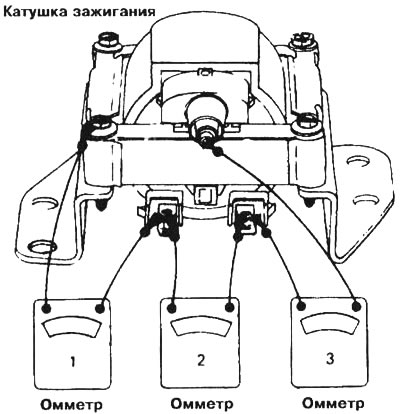
2. Check the ignition coil for opens and shorts to ground by performing the following three tests with an ohmmeter (see illustration).
7.2 To check the ignition coil, perform the following three tests using an ohmmeter: 1 - when…

7.2 To check the ignition coil, perform the following three tests using an ohmmeter: 1 - when setting the ohmmeter to measure high resistances, the device arrow should point to "infinity", 2 - when setting the ohmmeter to measure low resistances, the device arrow should point to a value close to zero, 3 - when setting the ohmmeter to measure high resistances, the device arrow should not point to "infinity". If the device readings differ from those given above, the coil should be replaced


3. Set the ohmmeter to the high resistance scale and connect the leads as shown in the illustration (see check N1 in illustration 7.2). The ohmmeter should show a very high resistance value or even "infinity". If the readings are different, replace the coil.

4. Set the ohmmeter to the low resistance scale and connect its terminals as shown in the illustration (see N₂ check in Illustration 7.2). The ohmmeter should show a very low resistance value, even zero. If other readings are present, replace the coil.


5. Set the ohmmeter to the high resistance scale and connect the leads as shown in the illustration (see check N3 in illustration 7.2). The ohmmeter should not show "infinity". If the measured resistance is "infinity", replace the coil.

Removal


6. Disconnect the high tension wire and both electrical terminals from the ignition coil.

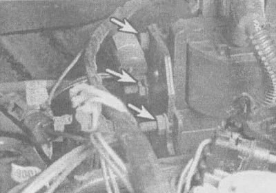
7. Unscrew the nuts (see illustration), remove the ignition coil from the engine.
7.7. Ignition coil mounting bolt locations (shown by arrows) on a 3.1 l engine

7.7. Ignition coil mounting bolt locations (shown by arrows) on a 3.1 l engine


Installation


8. Installation of the ignition coil is carried out in the reverse order.

Direct Ignition System (DIS)


Examination


9. First, refer to Section 6 and perform the ignition system checks described there.

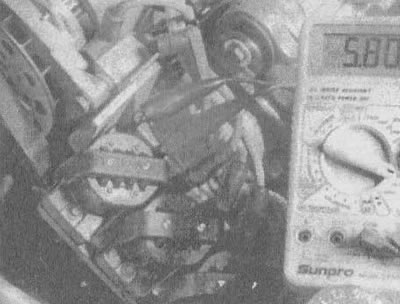
10. Using an ohmmeter, measure the resistance of the secondary winding of each coil (see illustration). The nominal resistance values are given in the technical specifications given in this chapter.
7.10 Measure the resistance of the secondary winding of each ignition coil

7.10 Measure the resistance of the secondary winding of each ignition coil


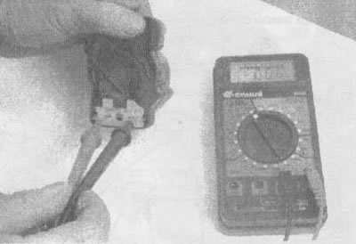
11. Then measure the resistance of the primary winding of each ignition coil (see illustration). The nominal resistance values are given in the technical specifications given in this chapter.
7.11 Measure the resistance of the primary winding of each ignition coil

7.11 Measure the resistance of the primary winding of each ignition coil


Replacement


12. Disconnect the cable from the negative terminal of the battery.

13. Disconnect all electrical contacts from the unit.

14. If the high-voltage wires are not numbered, number them and disconnect them from the coils (see illustration).
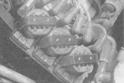
7.14. Each high-voltage wire has its own number, stamped on the top of the ignition coil

7.14. Each high-voltage wire has its own number, stamped on the top of the ignition coil


15. Loosen the bolts and remove the coils and ignition unit from the vehicle (see illustration).
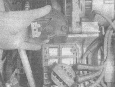
7.15. Carefully remove the coils from the ignition unit

7.15. Carefully remove the coils from the ignition unit


16. After unscrewing the bolts, disconnect the ignition coils from the block (see illustration 7.14).

17. Installation is carried out in reverse order.

18. When installing the ignition coils, ensure that their terminals are connected correctly.

[The text of the article was obtained from the website «CHEVYMAN»]

The article was checked: Vladimir Romannikov
This article is available at russian, bulgarian, belarusian, ukrainian, serbian, croatian, romanian, polish, slovak, hungarian

Share information:

Previous articles
Lumina 1: Engine electrical equipment
Next articles

Checking the ignition system
Ignition system — general information
Checking the condition and replacing the battery cables
Starting the engine from an auxiliary battery
Removal and installation the battery
Removal and installation the ignition distributor (3.1L engine)
Checking and replacing the ignition unit
Checking and replacing the inductive sensor (for 3.1L engines)
Battery Charging System — General Information and Precautions
Checking the charging circuit


See similar articles on the topic of Chevrolet cars:
Checking the ignition switch (lock) Chevrolet Aveo T300 (2012-2018)
Ignition coil Chevrolet Captiva 1 (2006-2018)
Checking ignition coils Chevrolet Cruze 1 (2008-2016)
Checking the condition of wheels and tires Chevrolet Lacetti 1 (2002-2009)
Checking the ignition coil and its circuits Chevrolet Lanos T150 (2002-2009)
Ignition switch Chevrolet Niva 1 (2002-2016)
Ignition Coil — Checking and Replacing Chevrolet Tahoe 1 (1992-2000)
Link in different formats to this page


Visitor comments

No comments yet


How much will 14 + 25 =


Orlando 1 (2010-2018) 
  • General information
  • Introduction to manual
  • User manual
  • Maintenance
  • Troubleshooting
  • Power unit
  • Engine repair
  • Fuel and control system
  • Cooling and lubrication system
  • Ignition system
  • Transmission
  • Clutch
  • Gearbox
  • Drive shafts
  • Chassis
  • Car suspension
  • Steering
  • Brake system
  • Body
  • Exterior (external elements)
  • Doors, locks and windows
  • Electrical equipment
  • Equipment and devices
  • Windscreen wipers
  • Power devices
  • Electrical diagrams


Trailblazer 1 (2001-2008) 
  • General information
  • User manual
  • Troubleshooting
  • Maintenance
  • Power unit
  • Engine in a car
  • Engine overhaul
  • Cooling and heating
  • Fuel and exhaust system
  • Engine electrical equipment
  • Engine control
  • Transmission
  • Automatic gearbox
  • Transfer case
  • Drive shafts and cardan
  • Chassis
  • Brake system
  • Car suspension
  • Steering
  • Body
  • Exterior (external elements)
  • Interior (internal elements)
  • Doors, locks and windows
  • Electrical equipment
  • Equipment and devices
  • Electrical circuits


Lumina 1 (1989-1994) 
  • General information
  • Maintenance
  • Power unit
  • Engine 3.1L V6
  • Engine 3.8L V6
  • Engine overhaul
  • Cooling system
  • Power and exhaust system
  • Fuel injection
  • Engine electrical equipment
  • Reduced exhaust gas toxicity
  • Transmission
  • Automatic gearbox
  • Drive shafts
  • Chassis
  • Brake system
  • Car suspension
  • Steering
  • Body
  • Heating and air conditioning
  • Repair of body elements
  • Doors, covers and windows
  • Interior (internal elements)
  • Electrical equipment
  • Equipment and devices
  • Electrical circuits


ChevyMan.ru © 2017-2026 · Mobile version · Feedback · Site search · Interesting to read · Sitemap: EN BG BY UA RS HR RO PL SK HU

Aveo 2003-2008 · Aveo 2006-2011 · Aveo 2012-2018 · Captiva 2006-2018 · Cruze 2008-2016 · Lacetti 2002-2009 · Lanos 2002-2009 · Niva 2002-2016 · Tahoe 1992-2000 · Tahoe 2000-2014 · Lumina 1 1989-1994 · Trailblazer 1 2001-2008 · Orlando 1 2010-2018 ·
🛡️ For your security and to improve our service, this site uses cookies. You can disable them in your browser.