
High Energy Ignition (HEI) System
Note: When checking or replacing the unit, it is not necessary to remove the ignition distributor.
Note: The terminal designations on the ignition unit are shown in Figure 6.5.
Examination
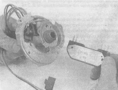
1. Disconnect the four-pin connector of the ignition distributor (see illustration).
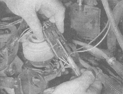
9.1 Using a small screwdriver, bend back the stopper on the ignition distributor connector
2. Check for spark on the ignition coil and on the wires (section 6).
3. If there is no spark, remove the distributor cap. Connect the four-pin connector to the distributor.
4. With the ignition switch in the "ON" position, measure the voltage at the positive ("+") terminal of the unit (pink wire) (see illustration).
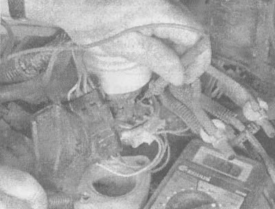
9.4 Measure the battery voltage by connecting the voltmeter lead to the positive terminal (pink wire) on the ignition unit
5. If the measured voltage is less than 10 V, the wiring between the positive terminal of the block and the positive connector of the ignition coil or between the ignition coil and the primary winding contact with the ignition switch is faulty.
6. If the measured voltage is equal to or greater than 10 V, check the condition of terminal "C" (brown wire) on the block (see illustration 9.4).
7. If the voltmeter shows less than 1 V, this means that there is a broken or shorted to ground wire in the section of the circuit between the distributor and terminal "C" of the coil, or an open primary circuit in the ignition coil itself.
8. If the device shows a voltage of one to ten volts, replace the unit with a new one and check for a spark (see section 6). The presence of a spark means that the unit was faulty and the system is now operating normally. If there is no spark, then the ignition coil is faulty.
9. If, when performing step 4, the voltmeter shows ten or more volts, disconnect the sensor terminal from the block. With the ignition on, measure the voltage at terminal "C" (brown wire) and, having connected for a short time (no more than five seconds) a test lamp between the positive terminal of the battery and the "P" terminal (output from the sensor, brown wire) on the block, observe the voltmeter readings (see illustration).
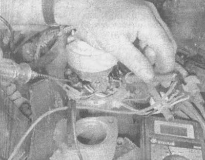
9.9. Having connected a voltmeter to terminal "C" (brown wire), watch carefully for voltage drop when turning on the test lamp for a short time (no more than five seconds) between the positive terminal of the battery and the "P" terminal (measuring coil) on the block body
10. If the voltage has not dropped, check the unit ground wire and, if it is not damaged, replace the unit with a new one.
11. If the voltage drops, disconnect the test lamp from the terminal on the block and check for a spark on the coil wire. If there is no spark, then the unit is faulty and requires replacement. The presence of a spark means that the sensor or connections are faulty or not connected to the "ground" (see illustration 9.9).
Replacement
12. Disconnect the cable from the negative terminal of the battery.
13. Remove the distributor cap and rotor.
14. After unscrewing both bolts securing the block, remove it from the distributor.
15. Disconnect both electrical terminals from the unit (see illustration). It should be borne in mind that these findings are not interchangeable.
9.15. Disconnect both electrical connectors from the unit
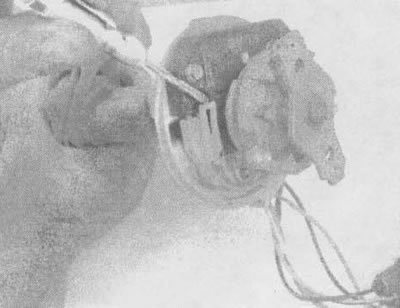
16. If you intend to install a block removed from the distributor on it, do not wipe off traces of grease from the block and the base of the distributor. When installing a new unit that comes with a package of silicone grease, wipe the unit and distributor housing clean, then apply a layer of this grease to the surface of the unit and distributor housing (see illustration). Lubrication serves to dissipate heat more efficiently.
9.16. Silicone grease applied to the base of the ignition distributor under the ignition unit helps dissipate heat more efficiently (for greater clarity, the distributor has been removed)
17. Install the block and connect both electrical terminals to it.
18. Install the rotor and distributor cap (see chapter 1).
19. Connect the cable to the negative terminal of the battery.
Direct Ignition System (DIS)
Examination
20. First of all, perform the ignition system checks presented in section 6.
21. To check the ignition unit, disconnect the 14-pin electrical connector from it (see illustrations).
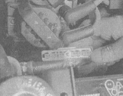
9.21a. Loosen the electrical connector and remove it from the ignition unit. The color coding of the wires and the connection diagram are shown in Figure 9.21b
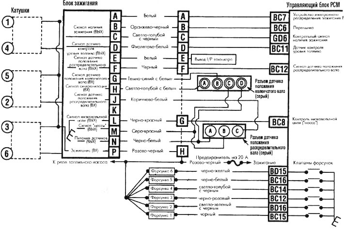
9.21b. Electrical connection diagram of the ignition system of the 3.8 L engine
22. Connect the injector testing lamp to the electrical contact of one of the injectors.
23. Turn on the ignition, connect one terminal of the test lamp to the positive terminal of the battery, and with the other several times touch the "D" terminal on the ignition unit (purple and white wire). At the same time, the injector test lamp should flash.
24. If the injector test lamp does not flash, check the injector electrical circuit section starting from the PCM control unit, or the fuel level monitoring sensor circuit starting from the ignition unit (see illustration 9.21b).
25. If the injector test lamp flashes, connect the wire from the fuse between the "N" terminal (black and white wire) on the ignition unit connector and the positive terminal of the battery. Connect the second same wire from the fuse between contact "M" (gray-red wire) and "ground". Connect a voltmeter between contact "H" (bluish-white wire) on the ignition unit connector and the positive terminal of the battery. While turning the crankshaft, note the instrument readings: the measured voltage should be approximately 1.7 V.
26. If the voltage is higher or lower than the specified value, check all electrical circuits from the ignition unit to the crankshaft position sensor for opens or short circuits.
27. If the measured voltage is 1.7 V, connect the tester between contact "G" (white and blue wire) on the ignition unit and the positive terminal of the battery. When the starter is rotating, the voltage should be 5.5 V.
28. If the voltage measured by the device is higher or lower than the specified value, check the blue and white wires from the crankshaft position sensor for a short circuit or an open circuit. Replace the sensor if necessary.
29. If the measured voltage is 5.5 V, connect the voltmeter between contact "P" (pink black wire) on the ignition unit connector and "ground". The device should show a voltage equal to the battery voltage.
30. If the measured voltage differs from the specified value, check and repair the pink/black ignition circuit wire from the ignition module to the fuel pump relay.
31. If the voltage is as specified, replace the ignition unit.
Replacement
32. Remove the coils separately from the ignition unit (see illustration 7.14).
33. Disconnect the electrical connector from the ignition unit.
34. Unscrew the bolts securing the ignition unit to the engine.
35. The unit is installed in the reverse order.