
Contents: General checks ↧ High Energy Ignition (HEI) System ↧ Direct Ignition System (DIS) ↧ Control unit with ignition coils ↧ The crankshaft turns but the engine… ↧
Caution: The ignition system contains extremely high voltage, so when performing any work on parts related to the ignition system, all safety precautions must be taken. This applies not only to the ignition distributor, control unit and high-voltage wires, but also to adjacent parts associated with this system, such as, for example, spark plug contacts, tachometer and any diagnostic equipment.
General checks
1. After turning the ignition key to the "ON" position and supplying voltage from the battery to the ECM/PCM electronic control unit, the service indicator light indicates the need for maintenance "SERVICE ENGINE SOON" ("Perform engine maintenance immediately").
2. Check all high-voltage wires for tightness, as well as for cuts, corrosion and other signs of poor contact. Incorrect connection or poor wire contact may cause ignition failure. Also check for carbon deposits inside the spark plug tips.
3. Using a spark plug tester, check that the secondary winding voltage (25,000 V) matches the spark plug voltage (see illustration).
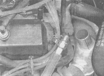
6.3. When using a calibrated ignition tester, disconnect the high-voltage wire from the spark plug, connect the tester to the nearest "mass" point (for example, to the valve cover bolt) and turn on the starter. If the high voltage is sufficient, a spark will jump between the end of the electrode and the tester body
4. Using an ohmmeter, measure the resistance of the wires. The resistance of each wire should be no more than 30,000 Ohms.
High Energy Ignition (HEI) System
5. On the attached diagnostic card (see illustration 6.5) the diagrams of the HEI ignition system test sequence are shown. The assignments of the contacts in the connector used to test the ignition unit are also shown.

Open large image in new tab →
6.5. Sequence diagram of ignition system testing on vehicles equipped with the HEI system
6. Test N1. Two high-voltage wires are tested to ensure that there are no breaks in these wires.
Check N1A: If spark occurs after disconnecting the 4-pin distributor connector, it means the output voltage level from the inductive pickup is too low for normal operation of the HEI system.
7. Checking N₂. The presence of a spark means that the distributor cap or its rotor is faulty.
Note: The occurrence of several sparks in a row, followed by their complete absence, should be assessed in the same way as the absence of sparks.
8. Check N3 (see illustration 6.5). Typically, the voltage at the "C" and "+" terminals should be equal to the voltage on the battery. A voltage below battery voltage indicates that the circuit from the distributor to the coil or to the ignition switch has very high resistance or is open. If the voltage at terminal "C" is low, and at terminal "+" it is 10 volts or higher, then the section of the circuit from terminal "C" to the ignition coil or to the primary winding of the ignition coil is broken.
9. Check N4 is used to detect a short circuit in the unit or a short circuit to ground in the section from the ignition coil to the unit. The ignition distributor block should be disconnected; in this case, the voltage in the circuit, provided that it is in good working order, should be about 12 V. If the unit is turned on, the voltage will drop, but will be higher than 1 V. This can lead to damage to the ignition coil due to overheating. When the primary winding of the ignition coil is open, only a small portion of the voltage will flow through the block from the "BAT" terminal to the tachometer terminal.
10. When applying a voltage of 1.5-8 V to the "P" terminal of the unit, the latter should turn on, and the voltage at the tachometer terminal should drop to approximately 7-9 V.
11. Checking N5 allows you to determine the presence of faults in the unit and ignition coil, and also to find out whether the measuring sensor generates the appropriate signal to turn on the unit. This test can be performed using a 1.5-8 V battery. Using a test lamp allows you to test the "P" terminal with simpler means. To start the unit, you can also use some types of digital multimeters, setting them to measure small resistances (diode test position). In this case, the multimeter terminals will show a voltage sufficient to start the unit. The voltage value at the terminals when the multimeter is set to the resistance measurement position can be determined using a second measuring device or found out from its technical characteristics specified by the manufacturer in the multimeter instructions.
12. During the N6 test, with the unit switched off, the appearance of a spark is checked. If there is no spark, then most likely one of the ignition coils is faulty, because by this stage of the test most of the unit faults should already have been detected. GM HEI Block Tester (kent Moore J-24642-F or similar) allows you to determine which coil is faulty. If you do not have this device, contact your General Motors dealer for assistance.
Direct Ignition System (DIS)
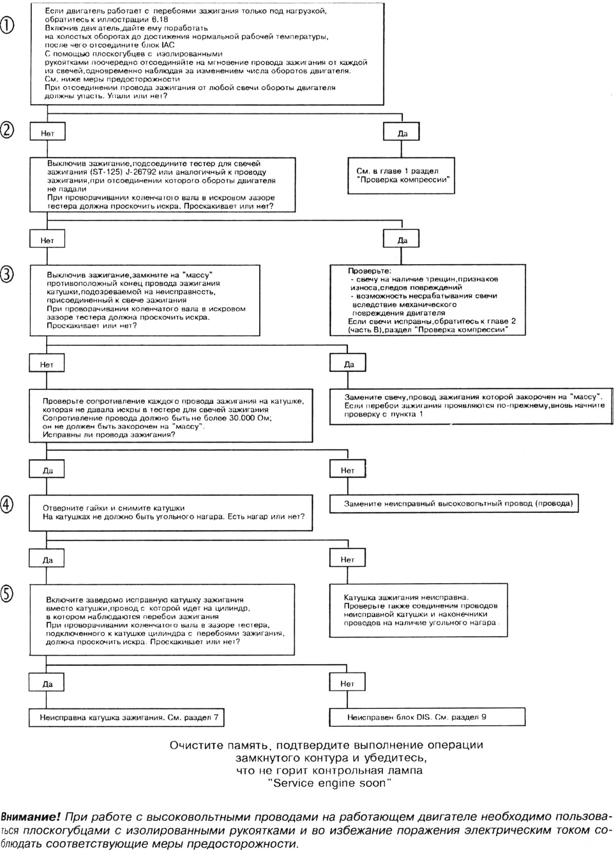
13. If misfiring occurs when the engine is idling, perform the first check indicated in the diagnostic chart (see illustration 6.13). If misfiring occurs when the engine is running under load, refer to the check shown in Illustration 6.18.
Open large image in new tab →
6.13. Sequence diagram for checking the direct ignition system when the engine is idling (checks 1-5)
14. Checking N₂. Using a spark plug tester, check that the voltage on the spark plug matches the voltage generated by the secondary winding of the coil (25,000 V).
15. Check N3. If after shorting the opposite ignition wire to ground a spark jumps in the spark gap of the tester, this means that the resistance of the spark plug in which the misfire occurs is too high. In addition, misfires may be caused by poor contact between the spark plug and the wire. Also check if there is any carbon deposits inside the spark plug tip.
16. Check N4. If there is carbon deposits, replace the ignition coil and make sure that the ignition wire terminals of this coil are clean and tightly tightened. Excessively high wire resistance or loose connections can cause damage to the ignition coil.
17. Check N5. If the ignition misfires disappear when the coils are swapped, this means that the first coil is faulty. If they still occur, then the ignition unit is faulty. This test can also be performed by replacing the non-sparking coil with another one that is known to be working properly.
18. If the engine runs under load with misfiring, perform test N6, the description of which is given in the corresponding diagram. Use a spark plug tester to check the voltage at the spark plug (should be 25,000 V). A spark should jump across the spark gap of the device when it is connected to all four wires. This simulates the operating condition of the engine under load.

Open large image in new tab →
6.18. DIS system test sequence diagram when the engine is running under load (checks NN 6-9)
19. Check N7. If after shorting the opposite high-voltage wire to ground a spark jumps in the spark gap of the tester, this means that the resistance of the spark plug operating with ignition interruptions is too high. In addition, the cause of ignition interruptions may be a faulty or loose contact between the spark plug and the wire. Also check if there is any soot deposits inside the spark plug protective cover.
20. Check N8. If there is carbon deposits, replace the ignition coil and make sure that the ignition wire terminals of this coil are clean and tightly tightened. Excessively high wire resistance or loose connections can cause damage to the ignition coil.
21. Check N9. If, when replacing a suspect coil, one of the remaining ignition coils produces a spark regularly, this means that this coil is faulty. If the ignition misfires persist, the cause is a malfunction in the unit. This test can also be performed by replacing the non-sparking coil with another one that is known to be working properly.
Control unit with ignition coils
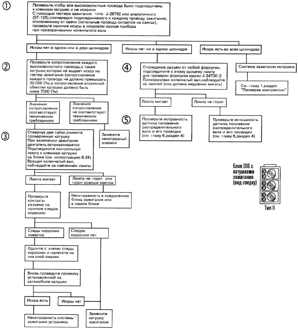
22. Test N1 allows you to check the system's ability to produce a voltage of at least 25,000 V.
Open large image in new tab →
6.22. DIS unit and ignition coil test sequence diagram (checks NN 1-5)
23. Checking N₂. If the high-voltage wire or secondary winding of the coil is open, sparks will not jump in the cylinder. Therefore, you should check both ignition wires of the coil and measure the resistance of its secondary winding. If the measured resistance is higher than the upper limit specified in the specifications, but less than "infinity", then such a coil will most likely allow the engine to start, but under certain circumstances it may cause its failure.
24. Check N3. Serves to check the serviceability of the starting circuit in the ignition unit (see illustration). Here the blinking lamp indicates that the unit is working properly.
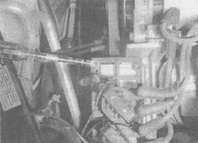
6.24. Having connected a test lamp to the terminals of the coil on the ignition unit, check whether it flashes when the crankshaft is turned
25. Check N4. Here, the slow blinking of the lamp means that the signal from the crankshaft position sensor does not reach the PCM (see illustration).
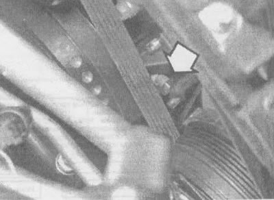
6.25. The crankshaft position sensor on the 3.8 L engine is located in the timing cover next to the crankshaft pulley
26. Check N5. In this case, the blinking of the lamp means that the camshaft position sensor and its control circuits are in good working order. The fault may be in the position sensor, in the sensor's electrical circuits, or in the ignition unit.
27. Checking N6. After turning on the ignition, listen to the operation of the fuel pump for the first two seconds. If it works, it means the fuse is intact.
28. Test N7. Allows you to determine whether the cause of the malfunction is a short circuit to ground of the signal from the crankshaft position sensor or a malfunction in the signal circuit of the camshaft position sensor (see chapter 6, section 4).
29. The ignition unit supplies power to the sensor. Check N8 (see section 9) allows you to determine the presence of a fault in the unit or in its electrical circuits.
30. Using test N6, you can determine whether the fuse is good. Test N9 allows you to determine where exactly the fault is located - in the section of the circuit between the fuse and the ignition unit or in the unit itself.
The crankshaft turns but the engine does not start
31. If, with the ignition on and the test terminal of the ALDL connector not shorted to ground, the test lamp "SERVICE ENGINE SOON" blinking, check ignition and PCM.
32. Installing a lamp to check the injectors (it can be purchased at almost every auto parts store), check if control signals are going from the PCM to the fuel injectors. Here, the blinking of the lamp will indicate that the PCM is controlling the operation of the injectors, and that the ignition control signal from the PCM coming to the PCM is correct.
33. Using a spark plug tester, check whether the problem is related to the ignition system or the fuel supply system (see illustration 6.3).
34. Check the correct operation of the fuel pump and the low fuel level signal relay (see chapter 4, section 3). After the ignition is turned on, the fuel pump should work for only two seconds.
35. Check if the PCM is receiving a control signal from the ignition system (see section 9).