
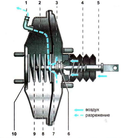
Schematic diagram of the brake booster: 1 - check valve; 2 - vacuum chamber; 3 - atmospheric chamber; 4, 9 - return springs; 5 — rod; 6 - double valve (vacuum and atmospheric); 7 - diaphragm; 8 - pusher; 10 — vacuum booster housing
The booster consists of two chambers 2 and 3, separated by a diaphragm 7. Chamber 2 of the booster, facing the main brake cylinder, is called vacuum, and chamber 3 on the brake pedal side is called atmospheric. The vacuum chamber is connected by a tube through a check valve 1 to the engine receiver, so when the engine is running, a vacuum is created in it. When the brake pedal is released, the double valve allows vacuum to pass into the atmospheric chamber 3 and blocks the flow of atmospheric air. As a result, the pressure on both sides of the diaphragm is the same. After pressing the brake pedal, the vacuum valve closes, and the atmospheric valve opens and through it outside air enters chamber 3. The pressure in it is compared with atmospheric pressure. At the same time, the vacuum in chamber 2 provides additional braking force. If the brake pedal is released, the return springs will move the rod and diaphragm to their original position and the vacuum in both chambers will equalize.
The check valve prevents the vacuum in chamber 3 from decreasing under various engine operating conditions. The outside air entering chamber 3 is cleaned by a special filter insert installed on the rod side.