ChevyMan.ru
Mazda Mitsubishi Toyota Land Rover Honda Kia Nissan
English Русский
Български
Беларускі
Український
Српски
Hrvatski
Română
Polski
Slovenský
Magyar
|
Articles | Sitemap | Contacts |


Home   Aveo   Captiva   Cruze   Lacetti   Lanos   Niva   Tahoe   Others  
Orlando 1 (2010-2018) Trailblazer 1 (2001-2008, petrol) Lumina 1 (1989-1994)
  • Home
  • Chevrolet
  • Orlando 1
  • Chassis
  • Brake system
  • Brake pedal position sensor

Brake pedal position sensor (Chevrolet Orlando 1)

            0

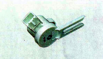
The brake pedal position sensor is a potentiometer, that is, a resistor with variable resistance.

The brake pedal position sensor is a potentiometer, that is, a resistor with variable resistance.


Brake Pedal Position Sensor Pins


Output designationPurpose of the output
A"Weight"
INSignal from the sensor
WITHSupply voltage 5V

The output signal from the sensor is analog and goes to the electronic control unit of the electrical equipment. Based on this signal, the unit issues a command to turn on the brake lights. Brake pedal position data may also be used by the engine management system, anti-lock brake system (ABS), and others.

The sensor is installed under the instrument panel on the brake pedal bracket. The sensor lever is engaged with the brake pedal.
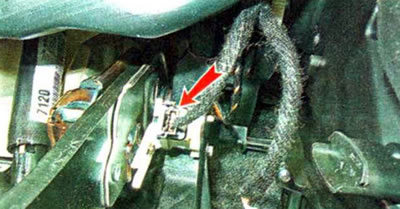
The sensor is installed under the instrument panel on the brake pedal bracket. The sensor lever is…


Checking and replacing the sensor


Warning. Do not remove the brake pedal position sensor unless necessary, as after installing it you will need to perform a sensor calibration procedure using a special diagnostic tool.


To perform the work you will need a multimeter and a special diagnostic device (scanner), which is described in the section "Engine Management System Diagnostics". We carry out the work in the following order:

1. We prepare the car for maintenance and repair.

2. To access the sensor, use a 7 mm socket wrench to unscrew the two bolts securing the instrument panel trim.
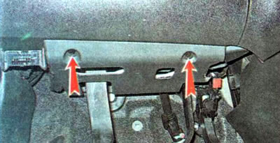
2. To access the sensor, use a 7 mm socket wrench to unscrew the two bolts securing the instrument…


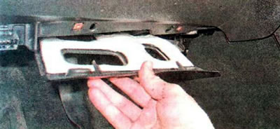
3. Remove the cover.

3. Remove the cover.


5. Press the lock and disconnect the wiring harness connector from the sensor.
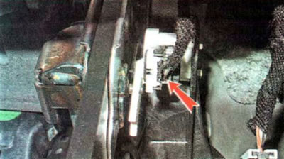
5. Press the lock and disconnect the wiring harness connector from the sensor.


4. Using a 7 mm wrench, unscrew the sensor mounting bolt...
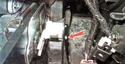


4. Using a 7 mm wrench, unscrew the sensor mounting bolt...


...and, having disengaged the sensor lever from the brake pedal pin, we remove the sensor.

5. Connect the multimeter in ohmmeter mode to terminals B and C of the sensor.
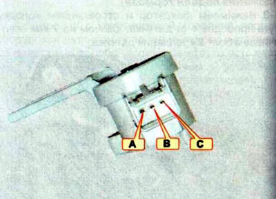
5. Connect the multimeter in ohmmeter mode to terminals B and C of the sensor.


Note: It is convenient to perform the test using an adapter to connect the device to the sensor. The adapter is a connecting block with wires. You can use short pieces (5-7 mm) of thin PVC tube. Place them on the sensor terminals and insert the multimeter probes into them. In this case, the device probes will be securely held in contact with the sensor terminals.


6. Turn the sensor lever, and its electrical resistance should smoothly change. If the resistance does not change or changes in leaps, replace the sensor.

7. Install the sensor in reverse order.


8. Install the instrument panel trim and secure it with bolts.

Note: After installing the sensor, it is necessary to calibrate it so that its initial parameters are registered in the electronic control unit of the electrical equipment. A special diagnostic tool is required to perform this procedure. If it is not available, you should contact a specialized service station; in case of self-calibration of the brake pedal position sensor, you must: secure the car with the parking brake. On a vehicle with an automatic transmission, turn the selector to position P. Connect the diagnostic device to the diagnostic connector block, as when diagnosing the engine management system, and be sure to delete the fault codes. Then, following the instructions for the device, you need to enter the BPP Sensor Calibration subsection (brake pedal position calibration) and then follow the instructions on the device display.


[The original text can be found on the website: chevyman.ru]

The article was checked: Vladimir Romannikov
This article is available at russian, bulgarian, belarusian, ukrainian, serbian, croatian, romanian, polish, slovak, hungarian

Share information:

Previous articles
Orlando 1: Brake system
Next articles

Checking the amplifier's functionality
Vacuum brake booster
Anti-lock braking system
Bleeding the brake hydraulic system
Windscreen washer — check, replacement
Brake fluid
Replacing brake fluid
Brake system — description and malfunctions


See similar articles on the topic of Chevrolet cars:
Checking the brake pedal position Chevrolet Aveo T300 (2012-2018)
Clutch pedal position sensor Chevrolet Captiva 1 (2006-2018)
Scheme 24. Steering wheel angular displacement sensors, accelerator pedal position sensors and ABS hydro-electronic module Chevrolet Cruze 1 (2008-2016)
Removal the crankshaft position sensor Chevrolet Lacetti 1 (2002-2009)
Checking the crankshaft position sensor and its circuits Chevrolet Lanos T150 (2002-2009)
Adjusting the position of the brake light switch Chevrolet Niva 1 (2002-2016)
Removal and installation the brake pedal position sensor Chevrolet Tahoe 2 and 3 (2000-2014)
Link in different formats to this page


Visitor comments

No comments yet


How much will 24 + 13 =


Orlando 1 (2010-2018) 
  • General information
  • Introduction to manual
  • User manual
  • Maintenance
  • Troubleshooting
  • Power unit
  • Engine repair
  • Fuel and control system
  • Cooling and lubrication system
  • Ignition system
  • Transmission
  • Clutch
  • Gearbox
  • Drive shafts
  • Chassis
  • Car suspension
  • Steering
  • Brake system
  • Body
  • Exterior (external elements)
  • Doors, locks and windows
  • Electrical equipment
  • Equipment and devices
  • Windscreen wipers
  • Power devices
  • Electrical diagrams


Trailblazer 1 (2001-2008) 
  • General information
  • User manual
  • Troubleshooting
  • Maintenance
  • Power unit
  • Engine in a car
  • Engine overhaul
  • Cooling and heating
  • Fuel and exhaust system
  • Engine electrical equipment
  • Engine control
  • Transmission
  • Automatic gearbox
  • Transfer case
  • Drive shafts and cardan
  • Chassis
  • Brake system
  • Car suspension
  • Steering
  • Body
  • Exterior (external elements)
  • Interior (internal elements)
  • Doors, locks and windows
  • Electrical equipment
  • Equipment and devices
  • Electrical circuits


Lumina 1 (1989-1994) 
  • General information
  • Maintenance
  • Power unit
  • Engine 3.1L V6
  • Engine 3.8L V6
  • Engine overhaul
  • Cooling system
  • Power and exhaust system
  • Fuel injection
  • Engine electrical equipment
  • Reduced exhaust gas toxicity
  • Transmission
  • Automatic gearbox
  • Drive shafts
  • Chassis
  • Brake system
  • Car suspension
  • Steering
  • Body
  • Heating and air conditioning
  • Repair of body elements
  • Doors, covers and windows
  • Interior (internal elements)
  • Electrical equipment
  • Equipment and devices
  • Electrical circuits


ChevyMan.ru © 2017-2026 · Mobile version · Feedback · Site search · Interesting to read · Sitemap: EN BG BY UA RS HR RO PL SK HU

Aveo 2003-2008 · Aveo 2006-2011 · Aveo 2012-2018 · Captiva 2006-2018 · Cruze 2008-2016 · Lacetti 2002-2009 · Lanos 2002-2009 · Niva 2002-2016 · Tahoe 1992-2000 · Tahoe 2000-2014 · Lumina 1 1989-1994 · Trailblazer 1 2001-2008 · Orlando 1 2010-2018 ·
🛡️ For your security and to improve our service, this site uses cookies. You can disable them in your browser.