Contents: Removal procedure ↧ Installation procedure ↧
Removal procedure
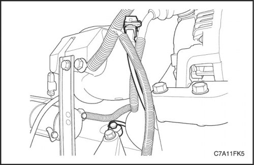
1. Disconnect the negative battery cable.
Caution! To prevent injury, do not remove the expansion tank cap when the engine and radiator are hot, as heat maintains pressure in the system. Hot fluid and steam may escape under pressure and cause burns.
2. Drain the coolant. See Section 1D2, Engine Cooling System - FAM II 2.4D.
3. Remove the engine cover.
4. Remove the direct ignition system (DIS) spark plug wires.
5. Disconnect the exhaust gas recirculation (EGR) valve connector, engine coolant temperature (ECT) sensor connector and direct ignition system (DIS) connector.
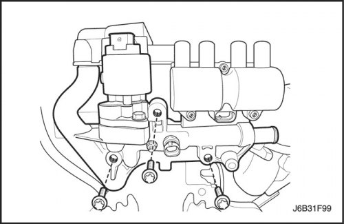
6. Disconnect the heater return hose on the exhaust gas recirculation (EGR) valve adapter.
7. Remove the exhaust gas recirculation (EGR) valve adapter mounting bolts.
8. Remove the exhaust gas recirculation (EGR) valve adapter and the positive crankcase ventilation system inner pipe with the gasket.
Installation procedure
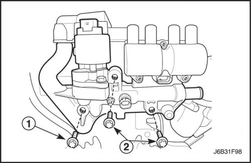
1. Install the exhaust gas recirculation (EGR) valve adapter and the inner pipe of the crankcase forced ventilation system with a gasket.
2. Install the exhaust gas recirculation (EGR) valve adapter mounting bolts.
Tighten
Tighten the exhaust gas recirculation (EGR) valve adapter mounting bolts (1) to 20 N·m (15 lb-ft).
Tighten the locking screws (2) of the EGR valve adapter to 30 Nm (22 ft·lbs).
3. Connect the heater return hose to the exhaust gas recirculation (EGR) valve adapter.
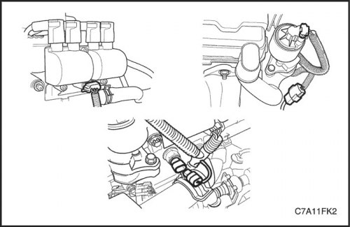
4. Connect the exhaust gas recirculation valve (EGR), coolant temperature sensor (ECT) and direct ignition system (DIS)connectors
5. Connect the ignition wire to the direct ignition system (DIS).
6. Install the engine cover.
7. Connect the negative battery cable.
8. Fill the engine cooling system.