


Contents: Wire Color Codes ↧ Connectors, grounding points and… ↧ Diagnostics and testing ↧ Lost and poor contact ↧ Troubleshooting Wiring ↧ Voltage measurement ↧ Conductivity test ↧ Finding a short circuit to "ground" ↧ Voltage Drop Test ↧ Connectors ↧ Diode ↧
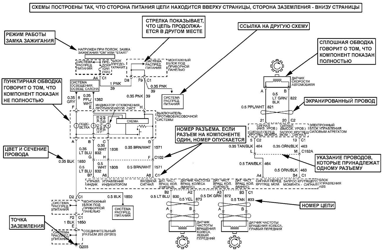
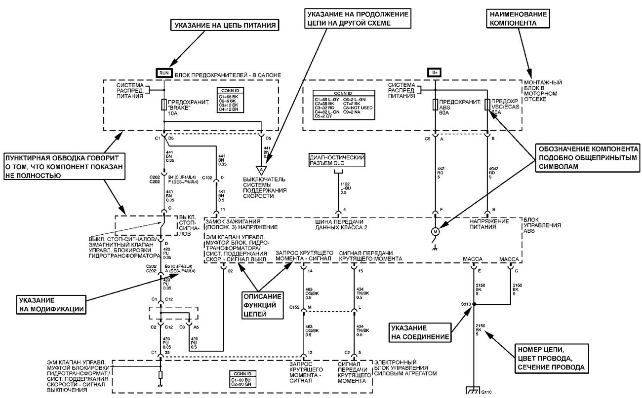
Wire Color Codes
The colors of the wires are indicated by capital Latin letters. The first letter indicates the main color of the wire, the second letter indicates the color of the strip.
| Designation | Color | |
| VK | BLK | black |
| OG | ORN | orange |
| BN | BRN | brown |
| RK | PNK | pink |
| GN | GRN | green |
| TN | TAN | yellow-brown |
| LB | LT BLU | blue |
| RD | RED | red |
| PU | PPL | purple |
| GY | GRY | grey |
| VT | violet | |
| BU | BLU | blue |
| WH | WHT | white |
| L-GN | LT GRN | light green |
| YE | YEL | yellow |
| D-BU | LT BLU | dark blue |
| D-GN | DKGRN | dark green |
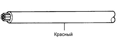 |
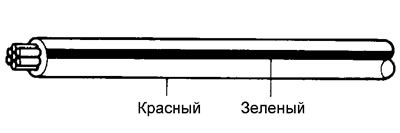 |
Connectors, grounding points and connections
Please note: Not all connectors can be repaired. Some connectors can only be replaced together with the wiring harness. A typical example is the connectors of the passive restraint system wiring. Always check the connector's ownership.
The connectors are numbered as follows:
- The connectors located in the engine compartment have C100 series numbers.
- The connectors located in the instrument panel area have series numbers C200.
- The connectors located on the body have the C300 series numbers.
- Remote connectors have C400 series numbers.
- Grounding points and grounding connectors are designated with the letter "G" and have a series number, just like the wiring connectors.
- Permanent connection locations are designated with the letter "S" and have a series number, just like wiring connectors.
- Component connectors are designated by the component name instead of numbers. If a component has more than one connector, additional numeric designations are used for identification, such as C1, C2, etc.
Diagnostics and testing
When troubleshooting an electrical circuit, there are a few common tools that you should have. These tools are listed below.
A jumper is a single wire used to connect two points in a circuit. It is used to bypass an open circuit.
Voltmeter - used to check the voltage in a circuit. Always connect the black probe to a good "ground" and the red probe to a positive point in the circuit.
Note: The voltmeter must have an input resistance of at least 10 MΩ.
Ohmmeter - used to check the resistance between two points in a circuit. Low or zero resistance in a circuit means good conductivity.
Note: The ohmmeter must have an input resistance of at least 10 megohms. Also, when checking the resistance, always turn off the power supply to the unit being tested, otherwise you may damage the device or get incorrect data.
Adapters - these tools are used when checking the terminals (pins) of the connector (figure 1). Select an adapter according to the terminal size and install it on the measuring instrument probe.
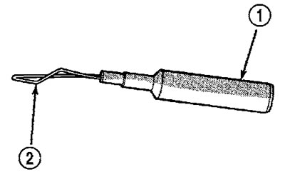
Figure 1. Adapter. 1 - end of the probe, 2 - end of the terminal
Lost and poor contact
Most electrical problems are caused by faulty connectors or wiring. Before deciding that a component or wiring is faulty, check the following:
- Reliability of connector connections.
- Status of connector contacts (connector fit, dirt, corrosion).
- Condition of the connector body.
- Condition of wire insulation (cuts, abrasions).
Troubleshooting Wiring
Note: When troubleshooting wiring, try to perform the following operations, this will make the search easier. Before any diagnostics, always check the equipment installed by yourself, included in the problematic circuit, it is advisable to disconnect this equipment altogether.
1. Formulate the problem correctly.
2. Check for any symptoms related to the problem. To do this, check all components included in the circuit, using the circuit diagrams.
3. Analyze the symptoms of the malfunction, determine the section of the circuit in which the malfunction with these symptoms is most likely to occur.
4. Isolate the problem area.
5. Make any necessary repairs.
6. Check the functionality of all components of this circuit.
Voltage measurement
1. Connect the negative probe of the voltmeter to a known good "ground" (figure 2).
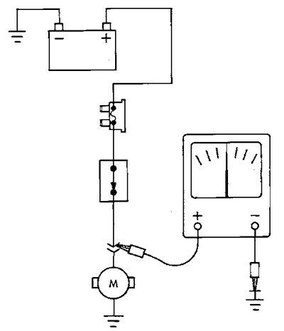
Figure 2. Voltage measurement
2. Connect the other voltmeter probe to the point of the circuit being tested. In some cases, it will be necessary to turn on the ignition.
Conductivity test
1. Remove the fuse for the circuit being tested or disconnect the battery.
2. Connect the ohmmeter probes to the points of the circuit being tested (figure 3). Low or zero resistance means good conductivity.
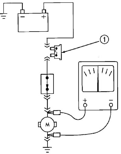
Figure 3. Checking the conductivity. 1 - removed fuse
Finding a short circuit to "ground"
Method 1
1. Remove the fuse and disconnect all components of the circuit protected by the fuse.
2. Connect a test lamp or voltmeter to the fuse socket terminals.
3. Starting from the fuse box, move the wire harness approximately every 15 - 20 cm and watch the voltmeter or test lamp.
4. If the voltmeter registers voltage or the test light comes on, there is a short to ground in that area of the wiring harness.
Method 2
1. Disconnect all components of the circuit whose fuse has blown.
2. Replace the blown fuse.
3. Turn on the ignition.
4. Start connecting the components of the circuit one by one. When the fuse burns out, you can say that the section of the circuit with a short circuit has been found.
Voltage Drop Test
1. Connect the positive lead of the voltmeter to the side of the circuit closest to the battery (figure 4).
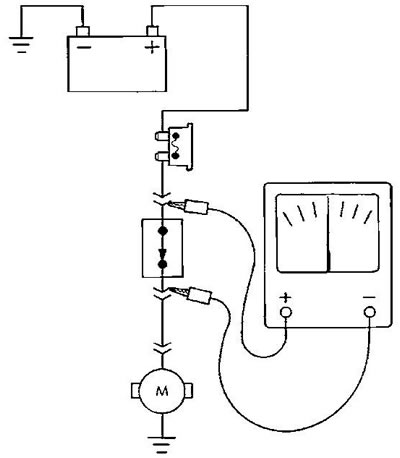
Figure 4. Checking the voltage drop
2. Connect the other voltmeter probe to the point in the circuit being tested.
3. The voltmeter will show the voltage difference between the two points.
Connectors
Replacing terminals
1. Disconnect the battery.
2. Release the connector lock.
3. Separate the halves of the connector.
4. Remove the protective cover (if applicable) (figure 5).
5. If necessary, release the secondary connector terminal retainer.
6. Using the special tool, release the primary locking clip of the connector terminal, pull the wire and remove the terminal from the connector body.
7. Installation is carried out in reverse order.
8. After connecting the battery, check the system's functionality.
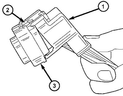
Figure 5. Removing the connector cover. 1 - cover, 2 - connector retainer, 3 - connector
Diode
Removal
1. Disconnect the battery.
2. Locate the diode in the wiring harness and remove the protective cover.
3. Remove the diode. Note the direction of current flow (figure 6).
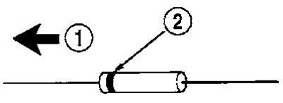
Figure 6. Diode identification. 1 - electric current, 2 - stripe around the diode indicates the direction of electric current
Installation
1. Strip the wire insulation enough to allow soldering of the new diode.
2. Install the diode in the wiring harness in the direction of the electric current flow. If necessary, refer to the corresponding circuit diagram.
3. Solder the diode. Use only rosin as a flux. Do not use acid flux.
4. Secure the diode to the harness with insulating tape.
The original source of the article is the website «ChevyMan.ru»