


Contents: Removal ↧ Installation ↧
Removal
1. Raise the vehicle.
2. Drain the oil from the front axle gearbox.
3. Disconnect the bridge actuator wiring connector.
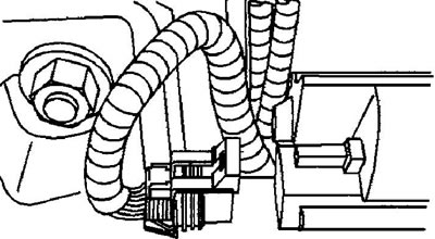
4. Release the axle drive wires from the support clip on the axle beam.
5. Remove the stabilizer bar links (9.25 inch gearbox) or shock absorber (8.25 inch gearbox).
6. Loosen the bolts securing the wheel drive shaft to the axle shaft.
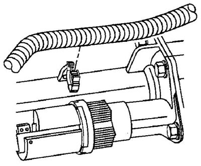
7. Unscrew the nuts securing the bridge beam to the bracket.
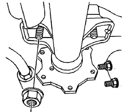
8. On 2500 and 3500 Series models, perform the following steps to provide additional work space:
- a) Loosen the nuts securing the front axle bracket to the frame.
- b) Move the front axle bracket towards the engine. You may have to pull the axle beam down and/or pull the bracket up.
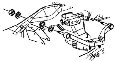
9. Loosen the bolts securing the axle beam to the gearbox housing.
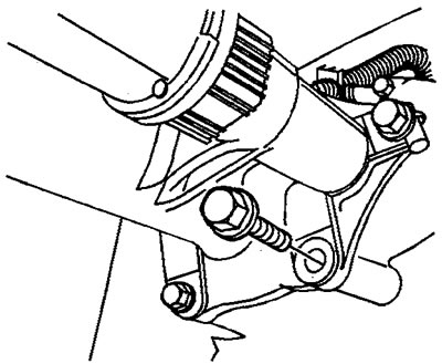
10. Carefully separate the axle beam from the differential housing.
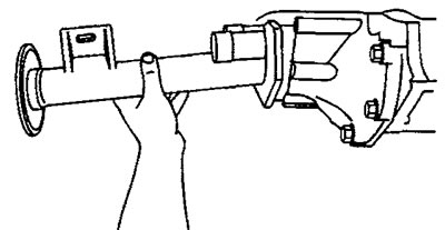
Caution: Keep the open end of the bridge beam up.
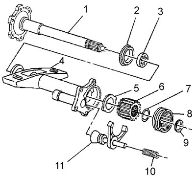
11. On models with an 8.25-inch gearbox, remove the following parts from the bridge beam:
Early models
- a) Inner spring (10) of the clutch fork.
- b) Clutch fork (11).
- c) Adjusting washer (9).
- d) Clutch (8).
- d) Clutch gear (6):
- clamp the bridge beam (4) in a vice by the mounting flange.
- using a hammer with a soft metal striker, knock the axle shaft (1) out of the gear (6) and remove the gear.
- e) Thrust washer (5).
Late models
- a) Inner spring (12).
- b) Clutch fork (11).
- c) Fork rod (10).
- d) Clutch (9).
- d) Axle shaft retaining ring (8).
- e) The first thrust washer (7).
- g) The second thrust washer (6).
- h) Laying the bridge beam (5).
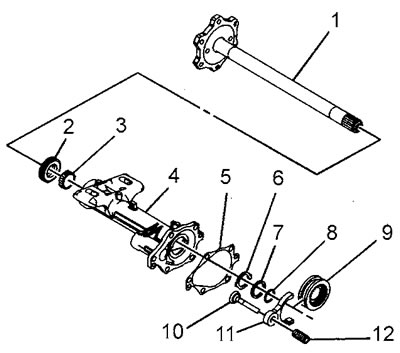
12. On models with a 9.25-inch gearbox, remove the following parts from the bridge beam:
- a) Inner spring (10) of the clutch fork.
- b) Clutch fork (11).
- c) Adjusting washer (9).
- d) Clutch (8).
- d) Retaining ring (7).
- e) Thrust washers (5) and (6).
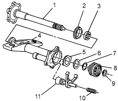
13. Remove the axle shaft (2) from the beam (1). If necessary, use a hammer with a soft metal striker.
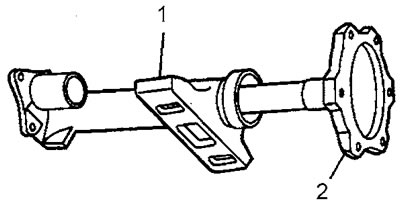
14. Remove the axle shaft seal and bearing from the beam
Installation
1. Install new axle shaft bearing and seal into the axle beam.
2. Install the axle shaft into the axle beam. If necessary, use a soft-faced hammer.
3. Install the axle shaft vertically onto the wheel drive shaft connection flange.
4. On models with an 8.25-inch gearbox, install the following parts:
Early models
- a) The thrust washer, aligning the projections of the washer with the grooves in the bridge beam. Recommendation: to hold the thrust washer in place, lubricate it with consistent grease.
- b) A lock washer into the clutch gear.
- c) The clutch gear onto the axle shaft until the locking ring snaps into place. If necessary, use a soft-faced hammer.
- d) An adjusting washer of the required thickness.
- e) Clutch.
- g) Clutch fork.
- c) Inner spring of the clutch fork.
Late models
- a) The second thrust washer.
- b) The first thrust washer.
- c) Axle shaft retaining ring.
- d) Clutch.
- d) Fork rod.
- e) Clutch fork.
- g) Inner spring.
- h) Laying the bridge beam.
5. On models with a 9.25-inch gearbox, install the following parts:
- a) The thrust washer, aligning the projections of the washer with the grooves in the bridge beam. Recommendation: to hold the thrust washer in place, lubricate it with consistent grease.
- b) The second thrust washer.
- c) Retaining ring on the axle shaft.
- d) An adjusting washer of the required thickness.
- d) Clutch.
- e) Clutch fork.
- g) Inner spring of the clutch fork.
6. Apply sealant to the bridge beam flange or install a new gasket.
7. Install the axle beam assembly onto the gearbox housing.
8. Install and tighten the axle beam to gearbox mounting bolts. Tightening torque: 8.25-inch gearbox 55 N·m; gearbox 9.25 inches 40 Nm.
9. On 1500 and 2500 series models:
- a) Move the front axle bracket toward the frame. Install the front axle bracket studs into the axle flange. You may have to pull the bracket up and/or pull the axle beam down to provide clearance for installing the studs.
- b) Tighten the nuts securing the front axle bracket to the frame. Tightening torque 90 Nm.
10. Tighten the beam mounting nuts to the bracket. Tightening torque 100 Nm.
11. Connect the wheel drive shaft to the axle flange. Tighten the mounting bolts. Tightening torque 80 Nm.
12. Install the stabilizer links or shock absorber.
13. Secure the bridge engagement drive wires to the bridge beam.
14. Connect the bridge actuator wiring connector.
15. Fill the gearbox housing with transmission oil.
16. Lower the vehicle.