


Note: The manufacturer recommends checking the bolt holes on the block for distortion, as well as the concentricity and alignment of the main bearing holes. Since this requires special measuring instruments, the test should be carried out in an auto repair shop.
1. Before testing, the unit must be cleaned as described in section 15.
2. Visually check the block for cracks and signs of corrosion. Check the condition of the threads in the bolt holes. In addition, it is recommended to check for hidden cracks in an auto repair shop, which has special equipment for this purpose. If any defects are found, the unit must be repaired (if possible) or be replaced.
3. Check the cylinder walls for scratches or signs of wear.
4. Measure the diameter of each cylinder at its top (just below the ledge), in the center and at the bottom, parallel to the crankshaft axis (see illustrations).
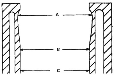
16.4a. Measure the diameter of each cylinder under the lip, from the groove (A), in the center (B) and at the bottom (C) |
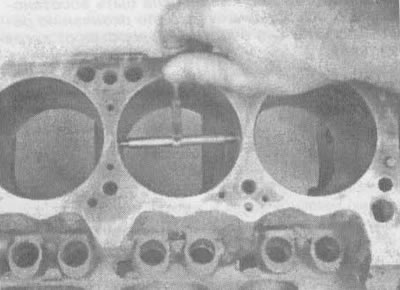
16.4b. The ability to "feel" when the bore gauge is in the correct position comes with time, so work slowly and repeat the check until you are confident that the measurement is correct |
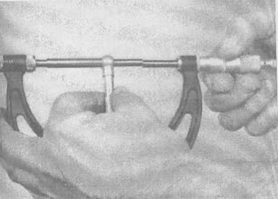
16.4v. The bore gauge diameter is then measured with a micrometer to determine the diameter value
Note: These measurements should not be taken with the block mounted separately on an engine stand - the cylinders will become distorted and the measurements will be inaccurate.
5. Next, measure the diameters of each cylinder in the same places, but across the crankshaft axis. Compare the results with the "Technical Data".
6. If you do not have the required precision measuring instruments, the clearances between the pistons and the cylinder walls can be determined (although not very accurate) using a set of feeler gauges. A standard set, commonly sold at auto parts stores, consists of feeler gauges of varying thicknesses and 12 inches long.
7. To check the clearance, select a feeler gauge and insert it into the cylinder with the corresponding piston. The piston must be installed in its normal operating position. The feeler gauge should be located between the piston and the cylinder on one of the thrust surfaces (at an angle of 90° to the hole for the piston pin).
8. The piston should slide inside the cylinder (with the dipstick inserted) with moderate resistance.
9. If it drops down or slides without resistance, the clearance is too large and the piston needs to be replaced. If the piston sticks at the bottom of the cylinder and passes freely at the top, the cylinder is taper. If areas of sticking are observed when rotating the piston with a feeler gauge in the cylinder, the cylinder is out of ovality.
10. Repeat this procedure for the remaining pistons and cylinders.
11. If there are noticeable scratches or abrasion marks on the cylinder walls, or if their ovality or taper exceeds the permissible values in the "Technical Data", take the cylinder block to an auto repair shop for cylinder boring and honing. After boring, it is necessary to install pistons and rings of a larger diameter.
12. If the cylinders are in reasonably good condition and not worn beyond acceptable limits and if the required clearance between the pistons and cylinders can be established, cylinder boring is not required. All that is required in this case is honing (see section 17).
The original article is on the website ChevyMan.ru