
Note: The crankshaft can only be removed after the engine has been removed from the vehicle. It is further assumed that the flywheel, anti-vibration device, timing chain, oil pan, oil pump and pistons with connecting rods have already been removed.
1. Before removing the crankshaft, check the axial clearance. Position the indicator so that its rod is in line with the crankshaft and touches one of the crankpins (see illustration).
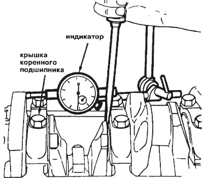
14.1. Checking the axial clearance of the crankshaft using an indicator
2. Move the crankshaft back to the limit and set the indicator scale to zero. Then move the crankshaft as far forward as possible and read the indicator reading. The measured distance is equal to the axial clearance. If its value exceeds the value specified in the technical conditions of this chapter, it is necessary to check the wear of the thrust surfaces of the crankshaft. If there are no visible signs of wear, the clearance can be adjusted by installing new bearings.
3. If you don't have an indicator, you can use feeler gauges. Carefully move the crankshaft all the way to the front of the engine. To determine the clearance, insert feeler gauges between the crankshaft and the front surface of the thrust main bearing (see illustration).
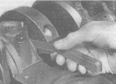
14.3. Checking the axial clearance of the crankshaft using a feeler gauge
Note: The thrust bearing is located at the N₂ cover (3.8L engine) or N3 (3.1L engine) main bearing.
4. Check the presence of indicator marks on the main bearing caps. They should be numbered sequentially from the front of the engine to the rear. If there are no marks, apply them using special stamps or a center punch (see illustration). The main bearing caps usually have arrows cast on them that point toward the front of the engine (see illustration). Loosen the main bearing cap bolts one at a time by 1/4 turn until they can be removed by hand. If studs are used anywhere, make sure they are returned to their original locations when reinstalling the crankshaft.
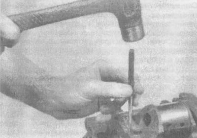
14.4a. Using a center punch or special stamp, mark the main bearing caps to ensure that they are installed in their original locations in the block (make marks with a center punch near the head of one of the bolts) |
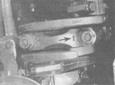
14.4b. The arrow on the main bearing cap points toward the front of the engine |
5. When removing the covers from the engine block, tap them lightly with a soft-faced hammer. If necessary, use the bolts as leverage when removing the covers. Be careful not to drop the bearing shells if they come out with the covers.
6. Carefully lift and remove the crankshaft from the engine. An assistant is required when performing this operation, as the crankshaft is quite heavy. Install the covers back into their original positions on the cylinder block and tighten the bolts by hand; in this case, the bearing shells must be in their places in the cylinder block and main bearing caps.
7. Remove the rear oil seal from the crankshaft.