
2. Install the engine so that its bottom is facing up.
3. Loosen the main bearing cap mounting bolts and remove the caps. Lay them out in the proper order to ensure proper installation.
4. Remove the old bearing shells from the block and main bearing caps if they are still there. Wipe the bearing surfaces of the block and covers with a clean, lint-free cloth. They must be kept in perfect cleanliness.
Checking the main bearing clearance
Note: Do not touch the surfaces of the new bearing shells with your fingers. Oil and acid on your skin can corrode bearings.
5. Wipe the backs of the new main bearing shells and install one of them into the main bearing seat in the block. If one of the bearings in the kit has a large groove, that bearing must be installed in the block. Install the other bearing from each set into the corresponding main bearing cap. Make sure the tabs on the bearing shells fit into the recesses in the block or cover.
Caution! The oil holes in the block must be aligned with the oil holes in the bearing shells. Do not hammer, scratch or abrade bearing surfaces. No lubricant is used.
6. The thrust bearing must be installed in cover and seat N3 for the 3.1L engine and in cover and seat N₂ for the 3.8L engine (counting from the front edge of the engine).
7. Wipe the bearing surfaces in the block and the journals under the crankshaft main bearings with a clean, lint-free cloth.
8. Check and clean all oil holes in the crankshaft, as any dirt from there will inevitably end up on the new bearings.
9. After making sure the crankshaft is clean, carefully install it into the main bearings.
10. Before final installation of the crankshaft, check the main bearing clearance.
11. Cut several pieces of Plastigage plastic gauging wire to the required size (the pieces should be slightly shorter than the width of the main bearings) and place one piece on each main journal of the crankshaft, parallel to the axis of the journal (see illustration).
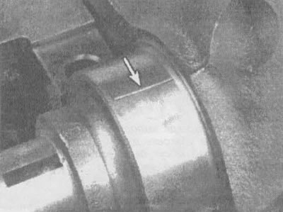
23.11. Place pieces of calibration wire on the journals under the main bearings parallel to the central axis of the crankshaft
12. Wipe the bearing surfaces in the caps and install the caps in their original places (don't confuse them!), and the arrows should point towards the front of the engine. Do not move the calibration wire.
13. Starting at the center main bearing and working outward, tighten the main bearing cap bolts in three stages to the torque specified in the specifications in this chapter. Do not turn the crankshaft during this operation.
14. Loosen the bolts and carefully remove the main bearing caps. Don't mix up the lids. Do not move the calibration wire or rotate the crankshaft. If any of the caps are difficult to remove, tap them lightly on the sides with a soft-faced hammer.
15. Compare the thickness of the flattened gauge wire on each journal with the scale printed on its package to determine the bearing oil clearance (see illustration). Compare the obtained result with the value from the "Technical data".
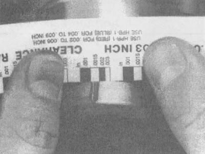
23.15. Measure the thickness of the flattened gauge wire to determine the clearance of the connecting rod bearings (don't confuse the scale - there are both inch and metric ones)
16. A clearance deviation from the required value may indicate a mismatch in the dimensions of the bearing shells and the need to replace them. Before replacing the bearings, make sure that no dirt has gotten between the bearings and the covers or block when measuring the clearances. If one end of the calibration wire is wider than the other, the neck is tapered.
17. Carefully clean all traces of gauge wire material from the shaft journals and/or bearing surfaces. Be careful not to scratch the bearing surfaces.
Installing the crankshaft
18. Carefully lift the crankshaft out of the engine.
19. Wipe the bearing surfaces in the block, then apply a thin, uniform coat of assembly motor oil or molybdenum-based grease to the surface of each bearing. Be sure to apply grease to the thrust surfaces and the surface of the thrust bearing journal. Install the rear oil seal (see section 25).
20. After ensuring that the crankshaft journals are clean, place the crankshaft back in the block.
21. Clean the bearing surfaces in the caps, then apply grease to them.
22. Install the covers in their original positions with the arrows pointing towards the front of the engine.
23. Insert the bolts.
24. Tighten all bolts (except for the thrust bearing cap bolts) moment specified in the technical data at the beginning of the chapter (work from the center outward and approach the final tightening torque in three stages).
25. Tighten the thrust bearing cap bolts to 10-12 ft-lbs.
26. Tap the ends of the crankshaft back and forth with a lead or brass hammer to align (arrange in one plane) thrust surfaces of the bearing and crankshaft.
27. Retighten all main bearing cap bolts to the torque specified in the specifications in this chapter, starting from the center and working outward.
28. Turn the crankshaft several times by hand to check for any noticeable binding.
29. The final operation consists of checking the axial play of the crankshaft using a feeler gauge or indicator in accordance with the procedure described in section 14. The axial clearance will be correct if the crankshaft thrust surfaces are not worn and new bearings have been installed.
(The original text can be found on the website ChevyMan)