
2. Remove the cover from the end of the connecting rod of the 1st cylinder (check the marks made during removal). Remove the original bearing shells and wipe the bearing surfaces of the connecting rods and cap with a clean, lint-free cloth. It is necessary to keep them spotlessly clean.
Installing the piston and checking the oil clearance of the lower connecting rod head liners
Note: Do not touch the surfaces of new bearing shells with your fingers. Oil and acid from your skin will contaminate the bearing surfaces.
3. Clean the back of the new upper bearing shell, then place it in place in the connecting rod. Make sure that the tab on the bearing fits into the recess on the connecting rod. Do not hammer the bearing shell into place, be very careful not to scratch the bearing surface. Do not lubricate the bearing at this stage.
4. Clean the back side of the other bearing and insert it into the connecting rod cap. Again, make sure the tab on the insert fits into the recess on the cover, do not apply any lubricant. When assembling, it is important to maintain perfect cleanliness and the absence of oil on the mating surfaces of the bearing and connecting rod.
5. Place the piston ring locks around the piston in a cross pattern (see illustration).
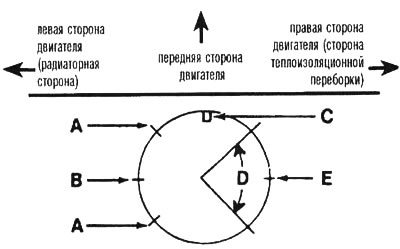
26.5. Location of ring locks: A - oil scraper ring, B - middle compression ring, C - recess in piston, D - expander, E - upper compression ring
6. Place a piece of plastic or rubber hose over each connecting rod cap bolt.
7. Lubricate the piston and rings with clean engine oil and install a piston ring compressor on the piston. Allow the skirt to protrude approximately 1/4 inch to guide the plunger in the cylinder. The rings must be compressed until they are flush with the piston.
8. Turn the crankshaft until the connecting rod journal of the 1st cylinder is at BDC, and apply a layer of clean engine oil to the cylinder walls.
9. Place the mark or notch on the top of the piston (see illustration) so that it is facing the front of the engine, carefully insert the piston into the 1st cylinder and install the lower edge of the mandrel on the engine block.
26.9. When installing pistons, the notch or arrow on each piston must be directed towards the front end of the engine (to the timing chain)
10. Tap the top edge of the mandrel to ensure that it contacts the block along the entire circumference.
11. With the connecting rod head positioned on the crankshaft journal, gently tap the top of the piston with the end of a wooden or plastic hammer handle (see illustration). The piston rings may try to jump up off the mandrel just before they enter the cylinder, so apply gentle downward pressure on the mandrel. Proceed slowly and if you feel resistance as the piston enters the cylinder, stop immediately. Find out the cause of the jam before continuing. Do not force the piston into the cylinder under any circumstances - this may break the ring and/or piston.
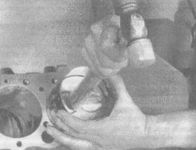
26.11. Carefully insert the piston into the cylinder using the end of a wooden or plastic hammer handle
12. Once the piston and connecting rod are installed, the big-end bearing clearance can be checked before permanently installing the cap and tightening the big-end bolts.
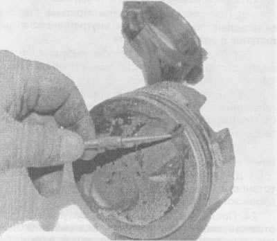
13. Cut a piece of Plastigage wire to the required size (slightly shorter than the width of the big end bearing) and place it on the connecting rod journal of the 1st cylinder, parallel to the axis of the journal (see illustration).
26.13. Place pieces of Plastigage wire on each journal under the connecting rod bearing parallel to the crankshaft axis
14. Clean the surface of the big end bearing cap, remove the protective sections of hose from the cap bolts and install the big end bearing cap. Make sure the mark on the cap is on the same side as the mark on the connecting rod.
15. Fit the nuts and tighten them to the torque specified in the specifications of this chapter. Carry out the tightening procedure in three stages.
Note: To avoid incorrect torque values due to the socket head becoming jammed between the connecting rod cap and the nut, use a socket head with thin walls. If there is a tendency for the head to jam between the cap and the nut, make sure that the head does not contact the cap (lift it slightly). When performing this operation, make sure that the crankshaft does not turn.
16. Remove the nuts and separate the big end cap - be careful not to touch the Plastigage wire.
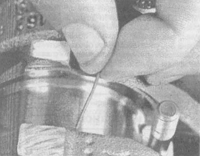
17. Compare the width of the flattened Plastigage wire with the scale printed on the wire package and determine the gap (see illustration). Compare it with the specifications in this chapter to check that its value is correct.
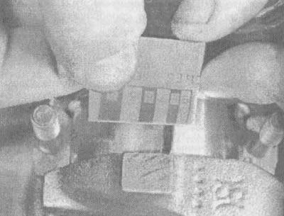
26.17. Measuring the width using Plastigage wire to determine the oil clearance of the connecting rod lower head bearings (make sure you use the correct scale - both inch and metric are available)
18. If the clearance does not meet the technical data requirements, this may mean that the bearing shell size has been selected incorrectly (and this means that other inserts will be required). Before deciding what size bearing shells are required, make sure there is no dirt or oil present when measuring the clearance between the bearing shells and the connecting rod or head cover. Also, check the neck diameter again. If the Plastigage wire is wider at one end than the other, then the neck has a taper (see section 19).
Installing the connecting rod
19. Remove all remaining Plastigage from the connecting rod journal and/or bearing surface. Be careful not to scratch the bearing.
20. Make sure the bearing surfaces are perfectly clean, then apply a uniform coat of clean molybdenum-based grease or a coat of special engine assembly oil to each of them. Push the piston into the cylinder with the bearing open on the connecting rod (don't forget to put the protective hoses on the connecting rod lower head cover bolts first).
21. Insert the connecting rod into its place on the journal, then remove the protective hoses from the connecting rod small end bolts, install the connecting rod cap and tighten the nuts to the torque specified in the specifications of this chapter. Perform the tightening in three stages.
22. Repeat the entire procedure with the remaining pistons and connecting rods.
23. It is very important to remember the following:
- a) When assembling, keep the reverse sides of the bearing shells and the inner sides of the connecting rods perfectly clean.
- b) Make sure to select the correct piston and connecting rod for each cylinder.
- c) The arrow or mark on the piston must point towards the front of the engine (where the timing chain is located).
- d) Lubricate the cylinder walls with clean engine oil.
- d) Lubricate the bearing surfaces when installing the connecting rod lower head caps after checking the clearance.
24. Once the pistons and connecting rods are properly installed, rotate the crankshaft by hand several times to ensure there is no noticeable binding.
25. Finally, it is necessary to check the axial clearance of the connecting rods (see section 13).
26. To ensure that the axial clearance value is correct, compare the obtained data with the technical specifications in this chapter. If the measurement was correct before the original crankshaft and rods were reinstalled, it should remain correct. If a new crankshaft or new connecting rods were installed, the end clearance value may be different. If this happens, the connecting rods will have to be removed and sent to an auto repair shop to be resized.
[The original source of the article is the website CHEVYMAN.RU]