ChevyMan.ru
Mazda Mitsubishi Toyota Land Rover Honda Kia Nissan
English Русский
Български
Беларускі
Український
Српски
Hrvatski
Română
Polski
Slovenský
Magyar
|
Articles | Sitemap | Contacts |


Home   Aveo   Captiva   Cruze   Lacetti   Lanos   Niva   Tahoe   Others  
Orlando 1 (2010-2018) Trailblazer 1 (2001-2008, petrol) Lumina 1 (1989-1994)
  • Home
  • Chevrolet
  • Lumina 1
  • Power unit
  • Engine overhaul
  • Installing piston rings

Installing piston rings (Chevrolet Lumina 1)

            0

1. Before installing new piston rings, it is necessary to check the gaps in the ring lock. It is assumed that the clearances in the piston ring groove have already been checked and are within normal limits (see section 18).

2. Lay out the piston assemblies with connecting rods and piston ring sets so that the ring set corresponds to the same piston and cylinder both when measuring the gaps in the lock and when assembling the engine.

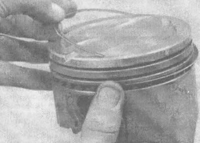
3. Insert the top (first) ring into the first cylinder and push it into the cylinder with the top surface of the piston (see illustration). The ring should be located at the bottom of the cylinder at the lower limit of the ring stroke.

22.3. When checking the gap in the piston ring lock, the ring must be inserted into the cylinder…

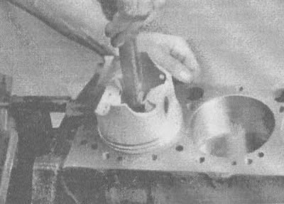
22.3. When checking the gap in the piston ring lock, the ring must be inserted into the cylinder (it can be pushed in there with a piston as shown in the illustration)


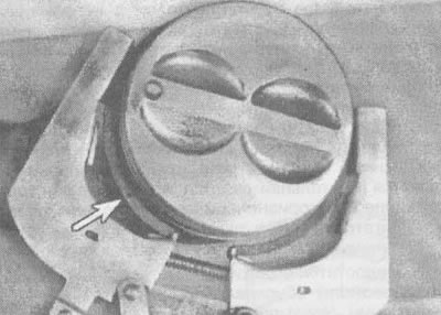
4. To measure the gap in the ring lock, insert feeler gauges between the ends of the ring until you select a feeler gauge equal to the width of the gap (see illustration). The feeler gauge should slide between the ends of the ring with slight resistance. Compare the measurement result with the figures given in the section "Technical data". If the gap is less or more than the required value, then before adjusting the gap, check again whether you have selected the right ring.


22.4. After inserting the ring into the cylinder, measure the gap between the ends of the ring…

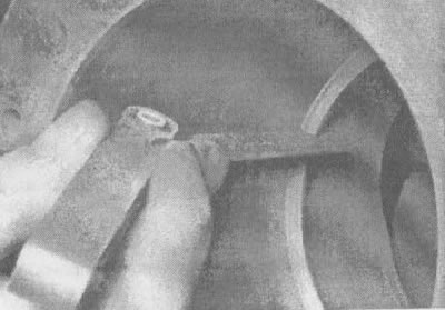
22.4. After inserting the ring into the cylinder, measure the gap between the ends of the ring using a feeler gauge


5. If the gap is too small, it should be increased, otherwise the ends of the ring may close during engine operation, which may lead to serious engine damage. The gap between the ends can be increased by carefully filing the ends of the ring with a fine-grain file. Secure the file in a vice with soft jaws, place the ring on the file so that its ends touch the surfaces of the file and, slowly moving the file, remove material from the ends. When performing this operation, grind the rings only with a movement towards the inside of the ring (see illustration).

22.5 If the gap between the ends is too small, clamp the file in a vice and file down the ends of…

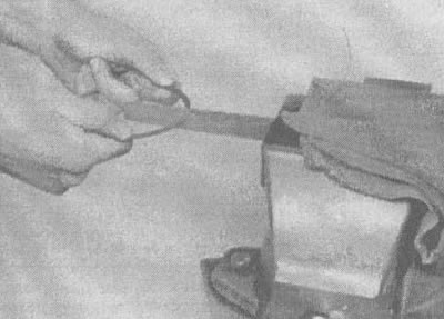
22.5 If the gap between the ends is too small, clamp the file in a vice and file down the ends of the ring (grind only from the outside to the inside) to increase the gap slightly


6. Excessive clearance becomes critical if it exceeds 0.040 inches. Check again that you have selected the correct rings.

7. Repeat the procedure for each ring that will be installed in the first cylinder, and for each ring in the remaining cylinders. The agreed piston-ring sets for each cylinder must not be disturbed.

8. After checking and adjusting the gaps, the rings can be installed on the pistons.

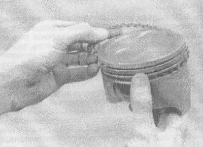
9. The oil scraper ring is installed first (the lowest ring on the piston). It consists of three separate parts. Insert the ring expander into the groove (see illustration). If an anti-roll insert is used, make sure it fits into the drilled hole in the ring groove. Then install the bottom part of the ring. When installing the ring parts, do not use a piston ring installer as this may break the ring parts. Instead, insert one end into the groove between the expander and the wall, hold it firmly in place, and slide your finger around the piston to push the ring into the groove (see illustration). Then insert the top part in the same way.

22.9a. Installing the expander into the oil scraper ring groove

22.9a. Installing the expander into the oil scraper ring groove
22.9b. Do not use piston ring pliers when installing the oil scraper ring side guides

22.9b. Do not use piston ring pliers when installing the oil scraper ring side guides


10. After installing the ring parts, check that both the upper and lower parts of the ring can rotate while sliding in the groove.

11. The second ring (the middle one) is installed next. It usually has a mark stamped on it, which should be directed towards the top of the piston.

Note: Always follow the instructions printed on the ring packaging - different manufacturers may have different requirements. Do not confuse the top and middle rings as they have different cross sections.


12. Use the piston ring installer and make sure the mark is facing the top of the piston, then install the ring into the middle groove on the piston (see illustration). Do not stretch the ring more than necessary to fit it onto the piston.

22.12. Installation of compression rings with ring expander. Label (shown by arrow) should be…

22.12. Installation of compression rings with ring expander. Label (shown by arrow) should be directed upwards


13. Install the first ring (upper) in the same way. Make sure that the mark is facing up. Be careful not to confuse the first and second rings.

14. Repeat the procedure for the remaining pistons and rings.

(The text of the article was obtained from the website: ChevyMan.ru)

The article was checked: Vladimir Romannikov
This article is available at russian, bulgarian, belarusian, ukrainian, serbian, croatian, romanian, polish, slovak, hungarian

Share information:

Previous articles
Lumina 1: Engine overhaul
Next articles

Engine Overhaul — Assembly Sequence
Checking main bearings and upper connecting rod bearings
Checking the crankshaft
Checking pistons and connecting rods
Cylinder honing
Installing the crankshaft and checking the crankshaft main bearing clearance
Installation of camshaft and balance shaft
Replacing the rear crankshaft oil seal
Installing and checking oil clearances of the lower connecting rod head liners
Removal and installation the flywheel


See similar articles on the topic of Chevrolet cars:
Setting the piston of the first cylinder to the TDC position Chevrolet Aveo T300 (2012-2018)
Connecting rod and piston group components Chevrolet Captiva 1 (2006-2018)
Setting the piston of the first cylinder to the TDC position of the compression stroke Chevrolet Cruze 1 (2008-2016)
Replacement of protective covers and sealing rings of pistons of brake cylinders of front and rear wheels Chevrolet Lacetti 1 (2002-2009)
Replacing the protective cover and sealing ring of the front wheel brake piston Chevrolet Lanos T150 (2002-2009)
Connecting rod and piston group Chevrolet Niva 1 (2002-2016)
Piston rings — installation Chevrolet Tahoe 1 (1992-2000)
Link in different formats to this page


Visitor comments

No comments yet


How much will 44 + 12 =


Orlando 1 (2010-2018) 
  • General information
  • Introduction to manual
  • User manual
  • Maintenance
  • Troubleshooting
  • Power unit
  • Engine repair
  • Fuel and control system
  • Cooling and lubrication system
  • Ignition system
  • Transmission
  • Clutch
  • Gearbox
  • Drive shafts
  • Chassis
  • Car suspension
  • Steering
  • Brake system
  • Body
  • Exterior (external elements)
  • Doors, locks and windows
  • Electrical equipment
  • Equipment and devices
  • Windscreen wipers
  • Power devices
  • Electrical diagrams


Trailblazer 1 (2001-2008) 
  • General information
  • User manual
  • Troubleshooting
  • Maintenance
  • Power unit
  • Engine in a car
  • Engine overhaul
  • Cooling and heating
  • Fuel and exhaust system
  • Engine electrical equipment
  • Engine control
  • Transmission
  • Automatic gearbox
  • Transfer case
  • Drive shafts and cardan
  • Chassis
  • Brake system
  • Car suspension
  • Steering
  • Body
  • Exterior (external elements)
  • Interior (internal elements)
  • Doors, locks and windows
  • Electrical equipment
  • Equipment and devices
  • Electrical circuits


Lumina 1 (1989-1994) 
  • General information
  • Maintenance
  • Power unit
  • Engine 3.1L V6
  • Engine 3.8L V6
  • Engine overhaul
  • Cooling system
  • Power and exhaust system
  • Fuel injection
  • Engine electrical equipment
  • Reduced exhaust gas toxicity
  • Transmission
  • Automatic gearbox
  • Drive shafts
  • Chassis
  • Brake system
  • Car suspension
  • Steering
  • Body
  • Heating and air conditioning
  • Repair of body elements
  • Doors, covers and windows
  • Interior (internal elements)
  • Electrical equipment
  • Equipment and devices
  • Electrical circuits


ChevyMan.ru © 2017-2026 · Mobile version · Feedback · Site search · Interesting to read · Sitemap: EN BG BY UA RS HR RO PL SK HU

Aveo 2003-2008 · Aveo 2006-2011 · Aveo 2012-2018 · Captiva 2006-2018 · Cruze 2008-2016 · Lacetti 2002-2009 · Lanos 2002-2009 · Niva 2002-2016 · Tahoe 1992-2000 · Tahoe 2000-2014 · Lumina 1 1989-1994 · Trailblazer 1 2001-2008 · Orlando 1 2010-2018 ·
🛡️ For your security and to improve our service, this site uses cookies. You can disable them in your browser.